
Aggregation of distributed energy resources

a distributed energy resource and energy resource technology, applied in the direction of electric controllers, ignition automatic control, instruments, etc., can solve the problems of under-utilization of dg assets, insufficient control and functional software to optimize the performance of dg assets, and increasing electric power consumption by businesses and industries. , to achieve the effect of reducing the demand of electric power

Inactive Publication Date: 2008-02-19
ENEL X NORTH AMERICA INC
View PDF24 Cites 267 Cited by
  • Summary
  • Abstract
  • Description
  • Claims
  • Application Information

AI Technical Summary

Benefits of technology

This system enables optimal utilization of distributed energy resources, reducing energy costs by up to 33% and improving reliability, allowing businesses to participate effectively in wholesale markets and access new revenue streams through coordinated load management and energy optimization.

Problems solved by technology

Businesses and industry continue to require and consume increased amounts of electric power.
Most owners and operators of DG systems lack sophisticated controls and functional software to optimize the performance of their systems.
This usually results in under-utilization of DG assets and unfavorable economics for DG projects.
In addition, most end-users of electric power do not want to become experts in microgeneration.
While the number of DG assets increases, much of these sit idle, and owners lack the capability to access wholesale power markets or sell this excess generation capacity back to the electric power distribution grid.
Most facilities lack sophisticated controls and functional software to optimize the employment of temporary demand reduction systems or capabilities and to record this activity for historical tracking purposes and credit in wholesale power markets.
This usually results in an underutilization of demand reduction systems or capabilities and unfavorable economics for such projects.
While new “smart” appliances and other enabling technologies have become more common, much of this capacity sits idle, and owners lack the capability to access wholesale power markets or sell temporary demand reduction back to the electric power distribution grid.

Method used


Image

  • Aggregation of distributed energy resources
  • Aggregation of distributed energy resources
  • Aggregation of distributed energy resources

Examples


Embodiment Construction

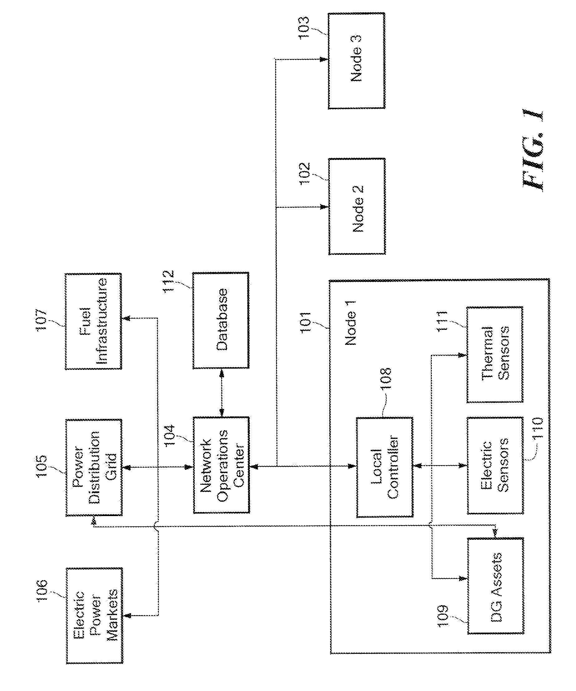
[0012]The present invention is directed to the remote management and control of distributed energy resources (DERs) including monitoring, alarming, control, aggregation, billing, data management, and reporting. Embodiments of the invention provide generation control and building energy management and control systems that are optimized for peak shaving and demand response activities, and which facilitate automation of various load curtailment-related strategies at the end-use level. Multiple distributed generation (DG) and other DER assets are networked in real-time within a single user interface for optimal control and verification. This creates an enabling technology system for facilitating customer or end-user participation in day-ahead or real-time electric power markets, and optimized utilization of DER assets.

[0013]More specifically, embodiments of the invention enable end-use electric power consumers and networked third parties to optimally aggregate and control DG and other D...


PUM


Abstract

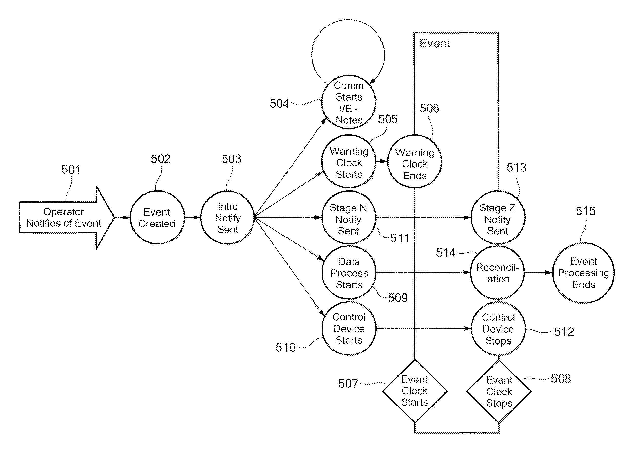
A method and system for controlling distributed energy resources is provided. Notification of an upcoming regional power distribution event is received and a distributed energy resource affected by the upcoming event is determined or identified. A first notification message is sent to an affected distributed energy resource asset owner or other administrator to notify the distributed energy resource asset of the event. An event data process is initiated to monitor and collect data associated with the event and an event control process is initiated to control one or more affected distributed energy resource asset during the event. The event control process and the event data process are terminated at the end of the event.

Description

[0001]This application is a continuation in part of U.S. patent application Ser. No. 10 / 314,920, filed Dec. 9, 2002, now U.S. Pat. No. 7,142,949 which provides priority for this application and which is incorporated herein by reference.FIELD OF THE INVENTION[0002]The invention generally relates to generation and consumption of electric power, and specifically, to aggregation of distributed energy resources.BACKGROUND ART[0003]Businesses and industry continue to require and consume increased amounts of electric power. One reflection of this trend is growing interest in self-generation of electric power, either to replace or to supplement that delivered by load-serving entities and utilities over the existing electric power distribution grid. Distributed energy resources (DER) are power generation technologies and demand reduction technologies located close to where electricity is used (e.g., a home or business) to provide an alternative to or an enhancement of the traditional electri...

Claims


Application Information

Patent Timeline
Patent Type & Authority Patents(United States)
IPC IPC(8): H02J3/00H02J3/14G06Q10/00H02J3/38H02J13/00
CPCG06Q10/00G06Q10/06H02J13/0006H02J3/381H02J13/001Y02E40/72Y04S10/40Y04S10/30Y02E60/74Y04S10/12H02J13/00001H02J13/00002Y02E40/70Y02E60/00
Inventor BREWSTER, DAVID B.HEALY, TIMOTHY G.
Owner ENEL X NORTH AMERICA INC
Learn More