
Laser pointer as auxiliary sight of firearm

a technology of laser pointer and firearm, applied in the field of laser pointers, can solve the problems of time-consuming and laborious, prior art suffered from disadvantage,

Inactive Publication Date: 2008-02-19
HSU YAO HSI
View PDF17 Cites 74 Cited by
  • Summary
  • Abstract
  • Description
  • Claims
  • Application Information

AI Technical Summary

Benefits of technology

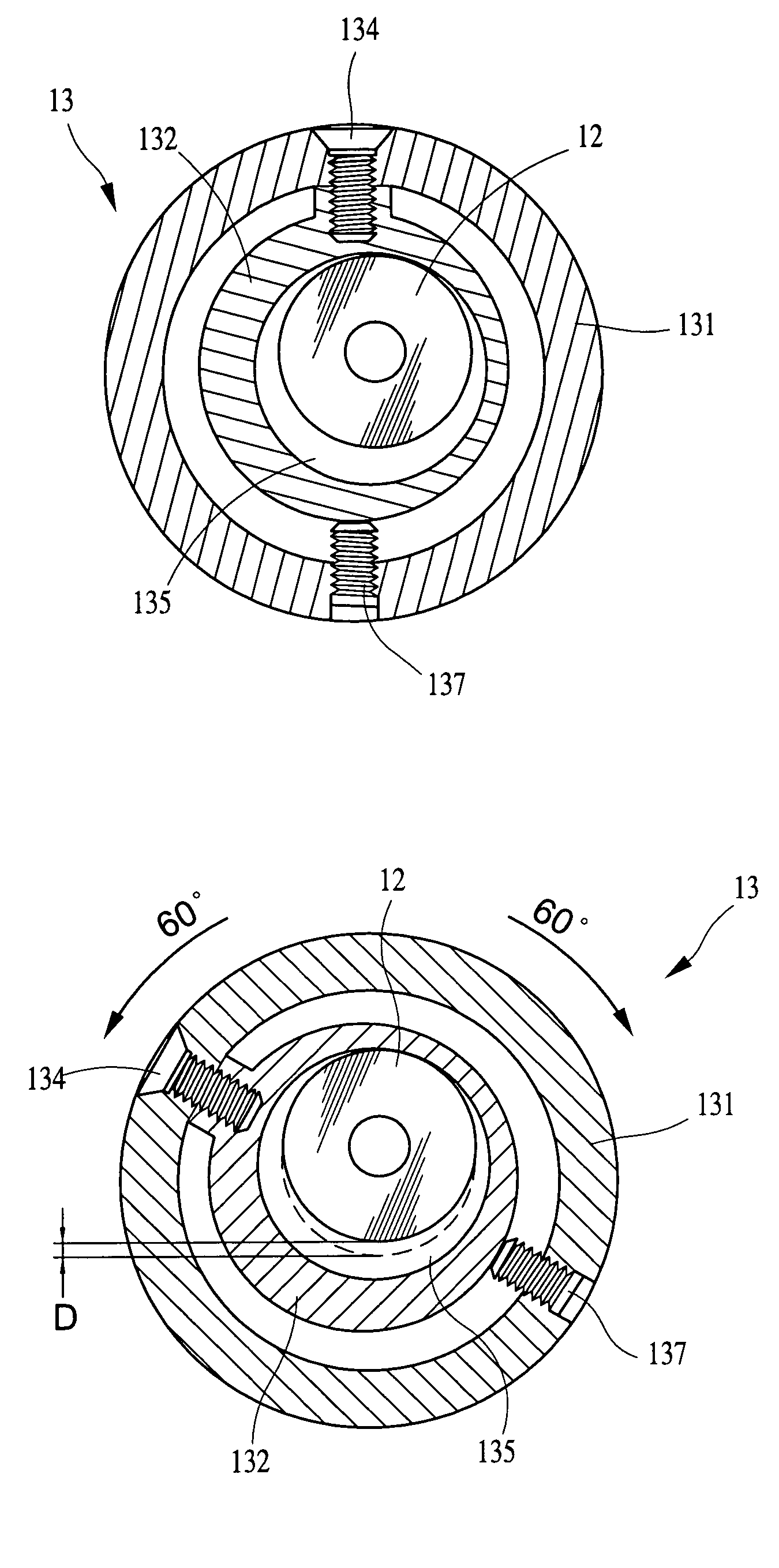
[0006]It is an object of the present invention to provide a laser pointer mounted on a seat of a firearm as an auxiliary sight, comprising a cylindrical housing comprising a forward aperture; a light emitting mechanism within the housing, the light emitting mechanism having a forward end fastened in the housing, the light emitting mechanism being adapted to emit laser beam through the aperture to impinge on a target; and an adjustment ring rotatably put on the housing, the adjustment ring comprising an outer knurled ring having a hole to permit a positioning fastener to drive through to urge the housing for fastening the corrected adjustment ring, and an inner cam ring comprising a projection on its outer surface to permit a fastener to drive through to threadedly secure to the knurled ring, an eccentric bore with a rear portion of the light emitting mechanism received therein, and a rear narrow shoulder as a stop. In operation, a rifle user can rotate the adjustment ring to adjust the laser beam direction and thus the light spot of the laser beam on the target. As such, it is possible of aiding the eyes to quickly line up the firearm on the target by only firing one or several shots.

Problems solved by technology

However, the prior art suffered from a disadvantage.
It is time consuming and tedious.

Method used


Image

  • Laser pointer as auxiliary sight of firearm
  • Laser pointer as auxiliary sight of firearm
  • Laser pointer as auxiliary sight of firearm

Examples


Embodiment Construction

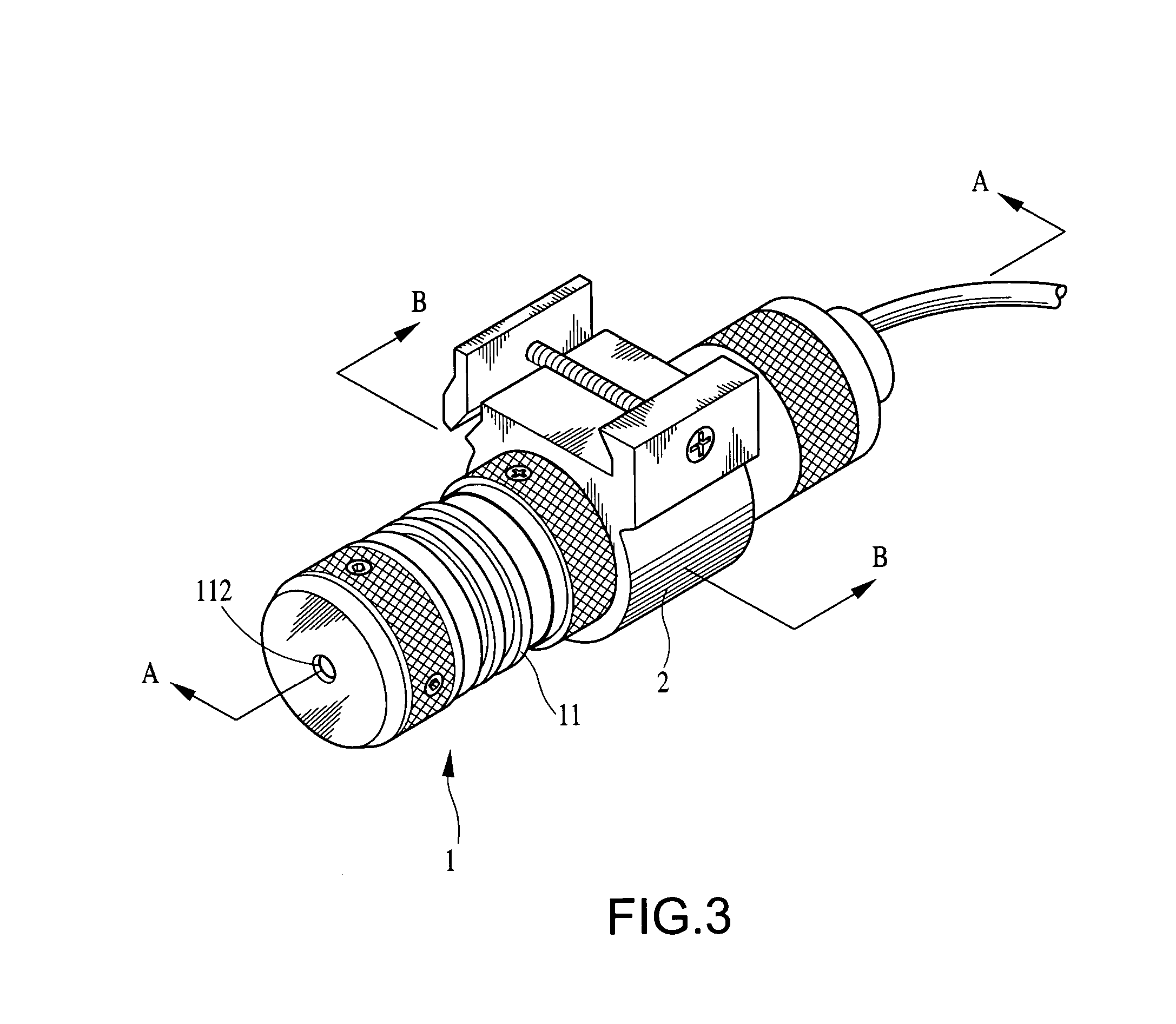
[0016]Referring to FIGS. 3, 4 and 5, a cylindrical laser pointer 1 constructed in accordance with the invention is shown. The laser pointer 1 is used as an auxiliary sight of a front sight of firearm (e.g., rifle). The laser pointer 1 comprises a housing 11 having an internal space for receiving a light emitting mechanism 12 and a cell (not shown) for supplying electrical energy to the light emitting mechanism 12 to emit light (e.g., laser beam in the embodiment) on an objective. A front end of the light emitting mechanism 12 is fastened in a bore 111 of the housing 11. Laser beam emitted from the front end of the light emitting mechanism 12 passes through a front aperture 112 of the housing 11. An interior cavity 113 of the housing 11 is formed to provide an allowance in adjusting the position of the light emitting mechanism 12 and thus the laser beam direction.

[0017]An adjustment ring 13 is provided at an intermediate section of the housing 11. In detail, the adjustment ring 13 is...


PUM


Abstract

A laser pointer on a seat of a firearm as an auxiliary sight is disclosed. The pointer comprises a cylindrical housing comprising a forward aperture; a light emitting mechanism in the housing, the mechanism being adapted to emit laser beam through the aperture to impinge on a target; and an adjustment ring rotatably put on the housing, the adjustment ring comprising an outer knurled ring, and an inner cam ring comprising an outer projection secured to the knurled ring, an eccentric bore for receiving a rear portion of the mechanism, and a rear narrow shoulder as a stop. A firearm user can rotate the adjustment ring to adjust the laser beam direction and thus the light spot on the target. The corrected adjustment ring can be fastened. Hence, the invention can aid the eyes to quickly line up the firearm on the target.

Description

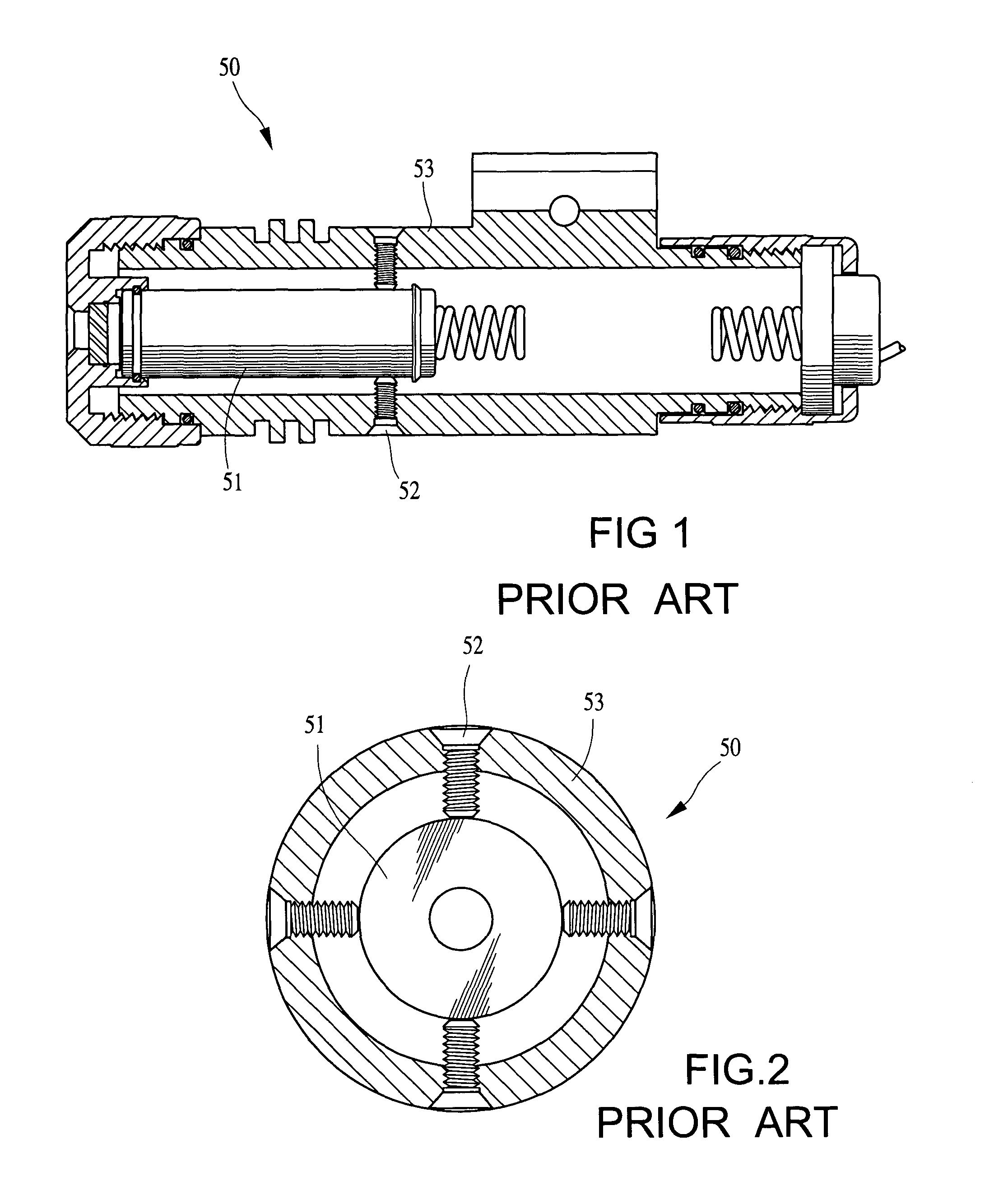
BACKGROUND OF THE INVENTION[0001]1. Field of the Invention[0002]The present invention relates to laser pointers and more particularly to a laser pointer used as an auxiliary sight of firearm (e.g., rifle) for aiding the eyes to quickly aim at a target.[0003]2. Description of Related Art[0004]A conventional laser pointer 50 is a battery operated, lightweight device as shown in FIG. 1. The laser pointer 50 comprises a front, internal light emitting mechanism 51 capable of emitting a laser beam on an objective. The prior laser pointer 50 is mounted on a seat of a firearm (e.g., rifle) for aiding the eyes to aim at a target. The laser pointer 50 is designed to be adjustable so that the laser beam emitted from the light emitting mechanism 51 can aid the eyes to line up the rifle on its target. The adjustment of the light emitting mechanism 51 is described below by referring to FIG. 2. A plurality of screws 52 are provided at a rear portion of the light emitting mechanism 51. Each screw 5...

Claims


Application Information

Patent Timeline
Patent Type & Authority Patents(United States)
IPC IPC(8): F41G1/00F41G1/28
CPCF41G1/35F41G11/003
Inventor HSU, YAO-HSI
Owner HSU YAO HSI
Learn More