
MTF measuring method and system

a technology of modulation transfer function and measuring method, which is applied in the direction of optical apparatus testing, radio frequency controlled devices, instruments, etc., can solve the problem of difficult and achieve the effect of high-precision measurement of m

Active Publication Date: 2008-02-12
GE MEDICAL SYST GLOBAL TECH CO LLC
View PDF14 Cites 6 Cited by
  • Summary
  • Abstract
  • Description
  • Claims
  • Application Information

AI Technical Summary

Benefits of technology

This approach enables highly precise detection of the LSF center and subsequent calculation of the MTF, enhancing the accuracy of X-ray CT system performance assessment.

Problems solved by technology

Since the detected center position is likely to contain an error because of the influence of noise, there is therefore difficulty in measuring the MTF highly precisely.

Method used


Image

  • MTF measuring method and system
  • MTF measuring method and system
  • MTF measuring method and system

Examples


Embodiment Construction

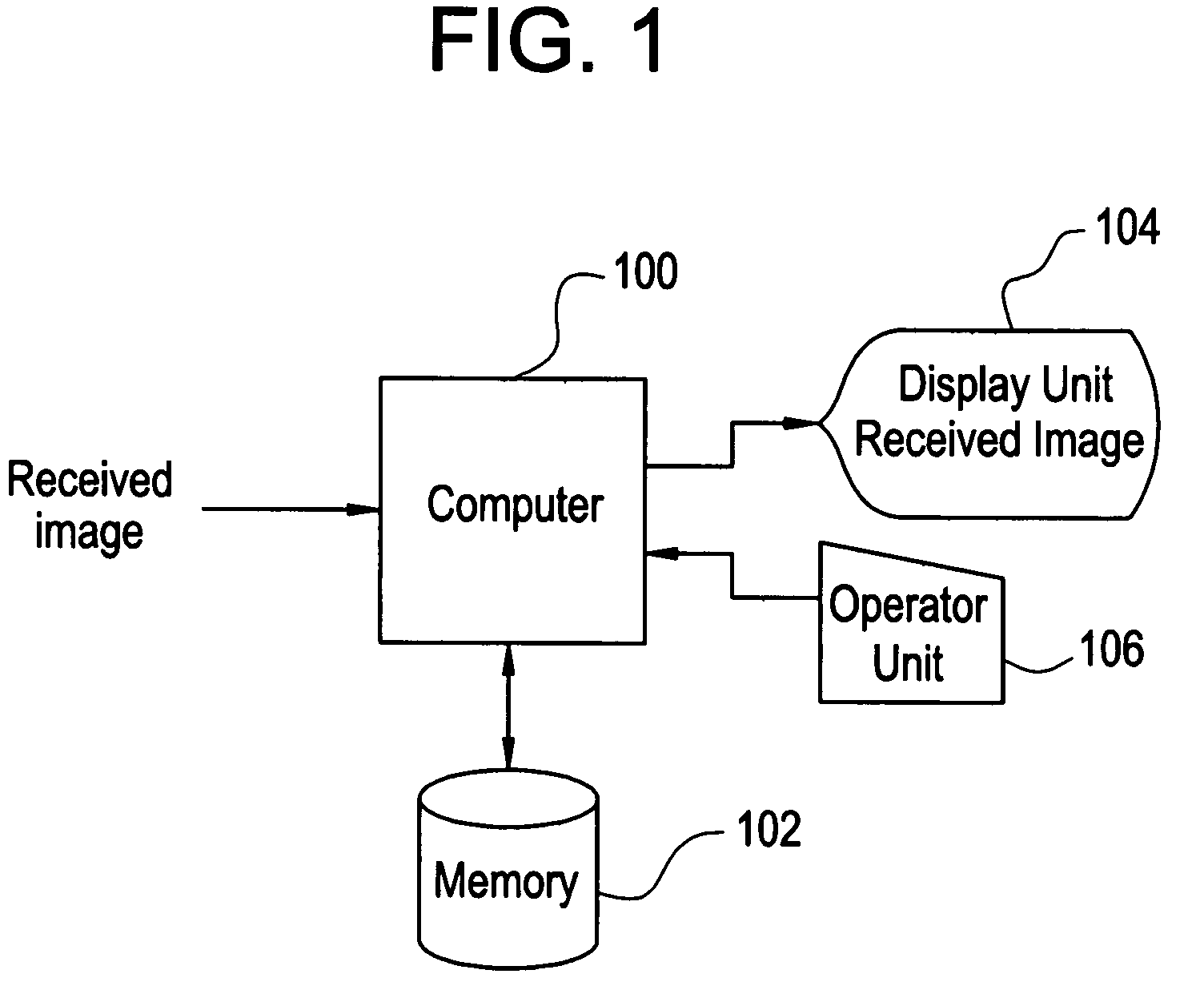
[0019]Referring to drawings, an embodiment of the present invention will be described below. FIG. 1 is a block diagram showing an MTF measuring system. The MTF measuring system is an example of the embodiment of the present invention. The components of the MTF measuring system signify an example of an MTF measuring system in accordance with the embodiment of the present invention. The actions of the MTF measuring system signify an example of an MTF measuring system in accordance with the embodiment of the present invention.

[0020]As shown in FIG. 1, the MTF measuring system includes a computer 100. The computer 100 receives an image, and includes a memory 102. The received image is stored in the memory 102. Moreover, various data items and programs to be used by the computer 100 are stored in the memory 102. The computer 100 runs the programs stored in the memory 102, whereby various kinds of data processing concerning MTF measurement are carried out.

[0021]The computer 100 also inclu...


PUM


Abstract

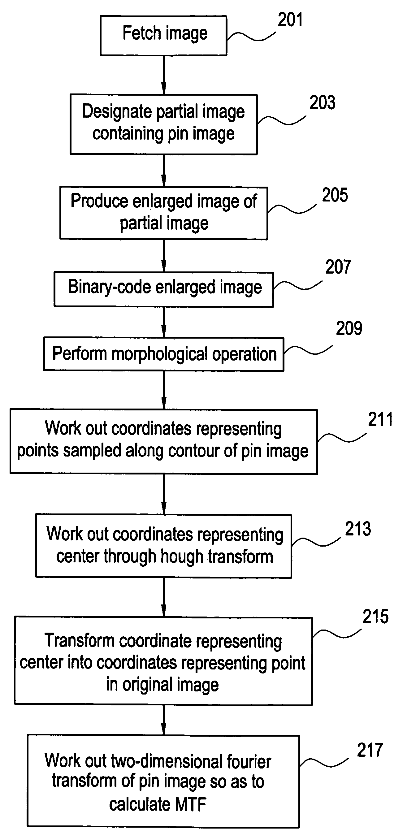
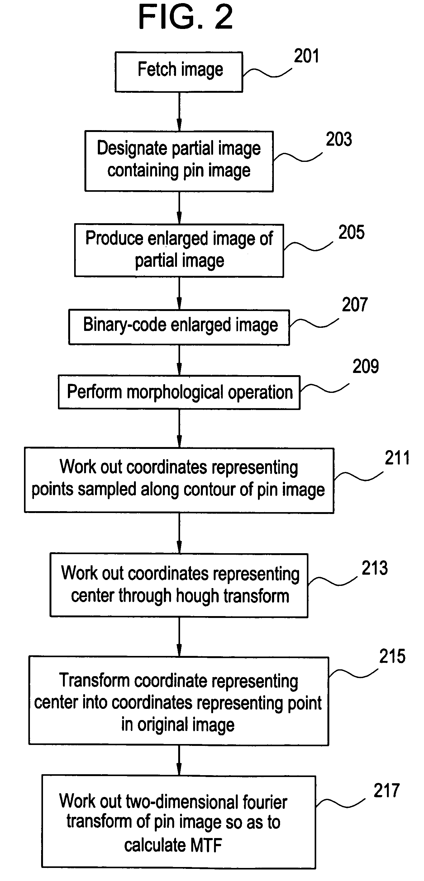
A method of measuring a modulation transfer function (MTF) includes detecting the center of a line spread function (LSF) image in order to calculate an MTF. For this purpose, an enlarged image of a portion of an image containing the LSF image is created, and binary-coded based on a threshold. A morphological operation is performed on the binary-coded image. Coordinates representing points that define the contour of the resultant image are sampled, and used to work out coordinates representing the center of a circle through Hough transform. The coordinates representing the center are transformed into coordinates representing a point in an original image.

Description

CROSS REFERENCE TO RELATED APPLICATIONS[0001]This application claims the benefit of Chinese Application No. 200310119694.2 filed Nov. 6, 2003.BACKGROUND OF THE INVENTION[0002]The present invention relates to an MTF (modulation transfer function) measuring method and system. More particularly, the present invention relates to a method and system for calculating an MTF by Fourier-transforming an LSF (line spread function).[0003]An MTF stands for a modulation transfer function, and indicates the spatial resolution of an image reconstructed by an X-ray computed tomography (CT) system. The MTF is therefore utilized in order to assess the performance of the X-ray CT system. The MTF is calculated by Fourier-transforming an LSF (line spread function) detected in the reconstructed image (refer to, for example, Non-patent Document 1).[0004][Non-patent Document 1]“Series of Advancements in Electronic Engineering No. 9 CT Scanner—X-ray Computed Tomography System” written by Yoshinori Iwai (Coro...

Claims


Application Information

Patent Timeline
Patent Type & Authority Patents(United States)
IPC IPC(8): G06K9/56H01L27/146A61B6/03G01M11/00G01M11/02G06F17/00G06K9/00G06K9/36G06T1/00G06T7/00G06T7/60
CPCG01M11/0292G06T7/004G06T7/606G06T7/70G06T7/66
Inventor WANG, XUELIYAN, XIONGWEIDING, WEIGOHNO, MAKOTO
Owner GE MEDICAL SYST GLOBAL TECH CO LLC
Learn More