
Security system for power and display of consumer electronic devices

a technology for electronic devices and security systems, applied in the direction of burglar alarms, mechanical actuation of burglar alarms, instruments, etc., can solve the problems of theft targeting of handheld consumer electronic devices, and achieve the effect of reducing the likelihood of providing an inappropriate voltage level, preventing and/or inhibiting an unauthorized removal

Inactive Publication Date: 2008-02-05
VANGUARD PRODS GROUP
View PDF22 Cites 129 Cited by
  • Summary
  • Abstract
  • Description
  • Claims
  • Application Information

AI Technical Summary

Benefits of technology

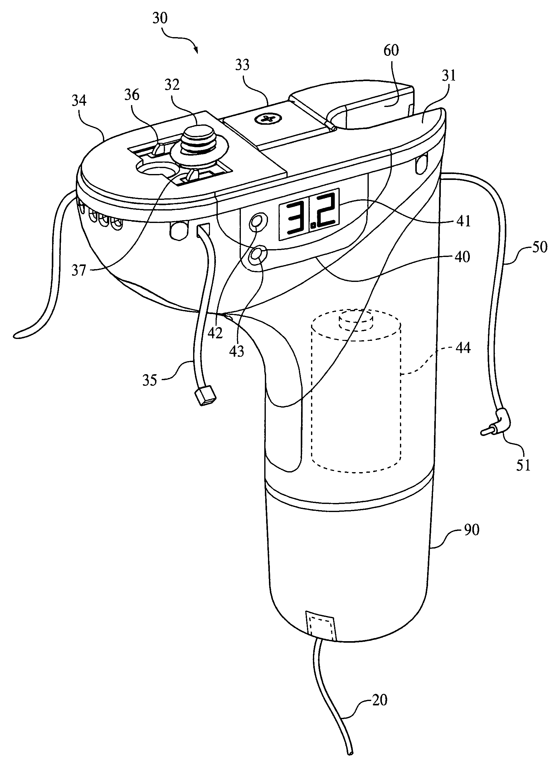
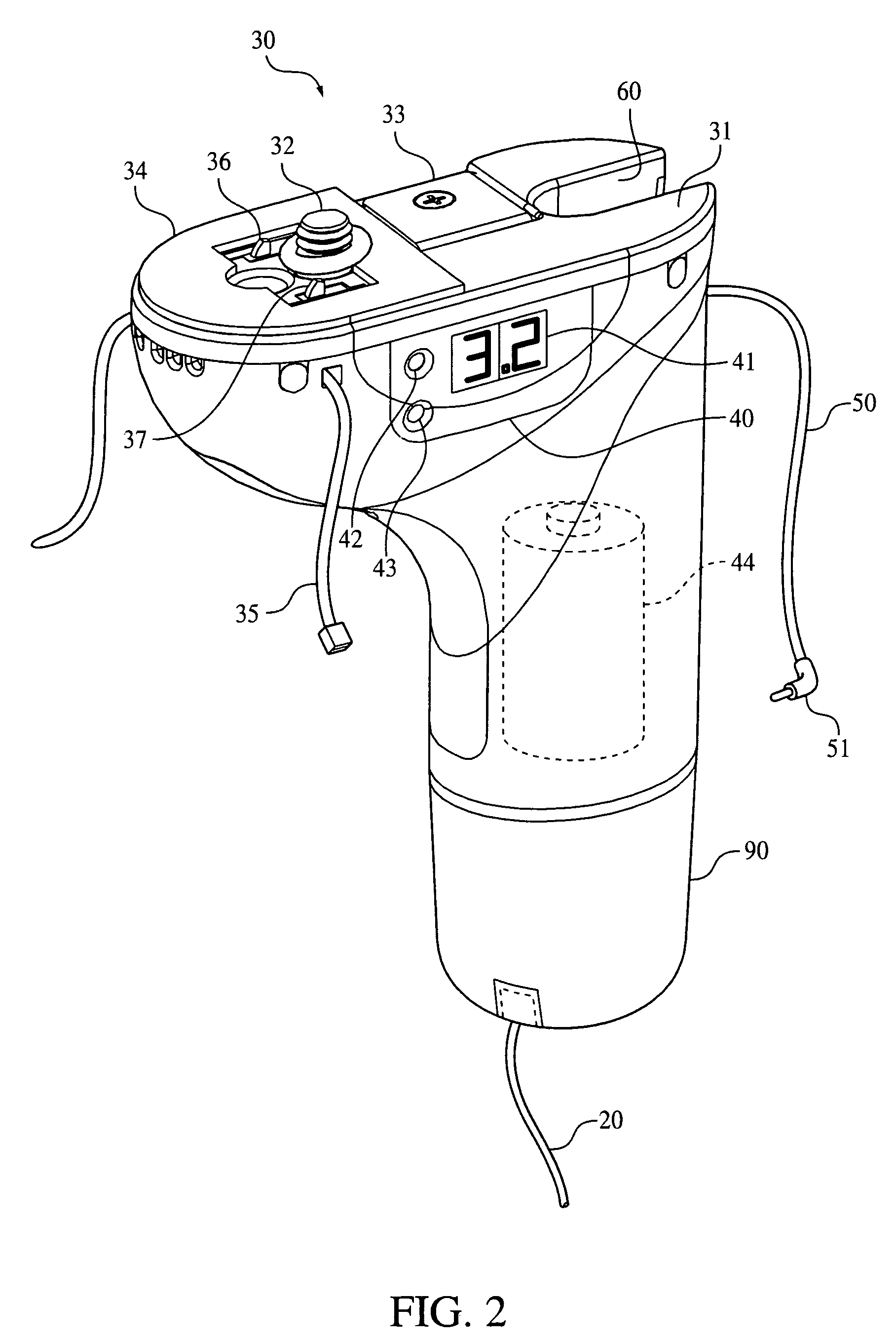
[0014]The handheld electronic device may be secured to the housing with a fastener, for example a threaded fastener which extends through a portion of the housing and engages an associated threaded aperture disposed on the handheld electronic device. In addition to or in place of a threaded fastener, a flexible locking band and / or an adhesive tape may be used to secure the handheld electronic device to the housing. A bracket may be provided on the top surface of the housing for preventing the handheld electronic device from rotating relative to the housing.
[0028]An advantage of a security system according to an embodiment of the invention is that an output voltage controller is provided for selecting an appropriate voltage to be delivered to a displayed electronic device. As voltage is selected and regulated via an adjustable output voltage controller, rather than by a power cable, the need for multiple power cables adapted for powering various electronic devices having differing input voltage requirements is eliminated.
[0029]Another advantage of a security system according to an embodiment of the invention is that an output voltage controller is provided wherein an output voltage may be set only when an electronic device to be powered is not coupled to a housing or a sensor coupled to the electronic device is not in a secure state. Furthermore, an output voltage to an electronic device is returned to zero if: 1) an electronic device is not coupled to the housing or a sensor coupled to the electronic device is not placed in a secure state within a predetermined period of time after setting an output voltage; or 2) if power to an electronic device has been enabled and the electronic device is removed from the housing or a sensor coupled to the electronic device is placed in a non-secure or alarmed state. These features greatly reduce the likelihood of providing an inappropriate voltage level to an electronic device via the output voltage controller, thereby damaging the electronic device.
[0030]Another advantage of a security system according to an embodiment of the invention is that an internal battery is provided for powering an output voltage controller disposed in a portable housing, so that a voltage level may be set and retained without the portable housing or output voltage controller being coupled to an external power source.
[0032]Another advantage of a security system according to an embodiment of the invention is that a bracket may be provided in a housing to which an electronic device is secured, wherein the bracket prevents the electronic device from rotating with respect to the housing, thereby preventing and / or inhibiting an unauthorized removal of the electronic device from the housing.
[0033]Another advantage of a security system according to an embodiment of the invention is that a notch may be provided in a portion of a housing where a power cable supplying power to a secured electronic device is coupled to the housing. The notch may serve to prevent or inhibit an unauthorized removal of the power cord once the electronic device has been secured to the housing. The power cord may be situated in the housing such that once the power cord and sensor are coupled to the housing, the power cable cannot be removed from the housing without first removing the sensor from the housing, thereby securing the power cable.

Problems solved by technology

Due to their small size, accessability and value, displayed handheld consumer electronic devices are often targeted for theft.

Method used


Image

  • Security system for power and display of consumer electronic devices
  • Security system for power and display of consumer electronic devices
  • Security system for power and display of consumer electronic devices

Examples


Embodiment Construction

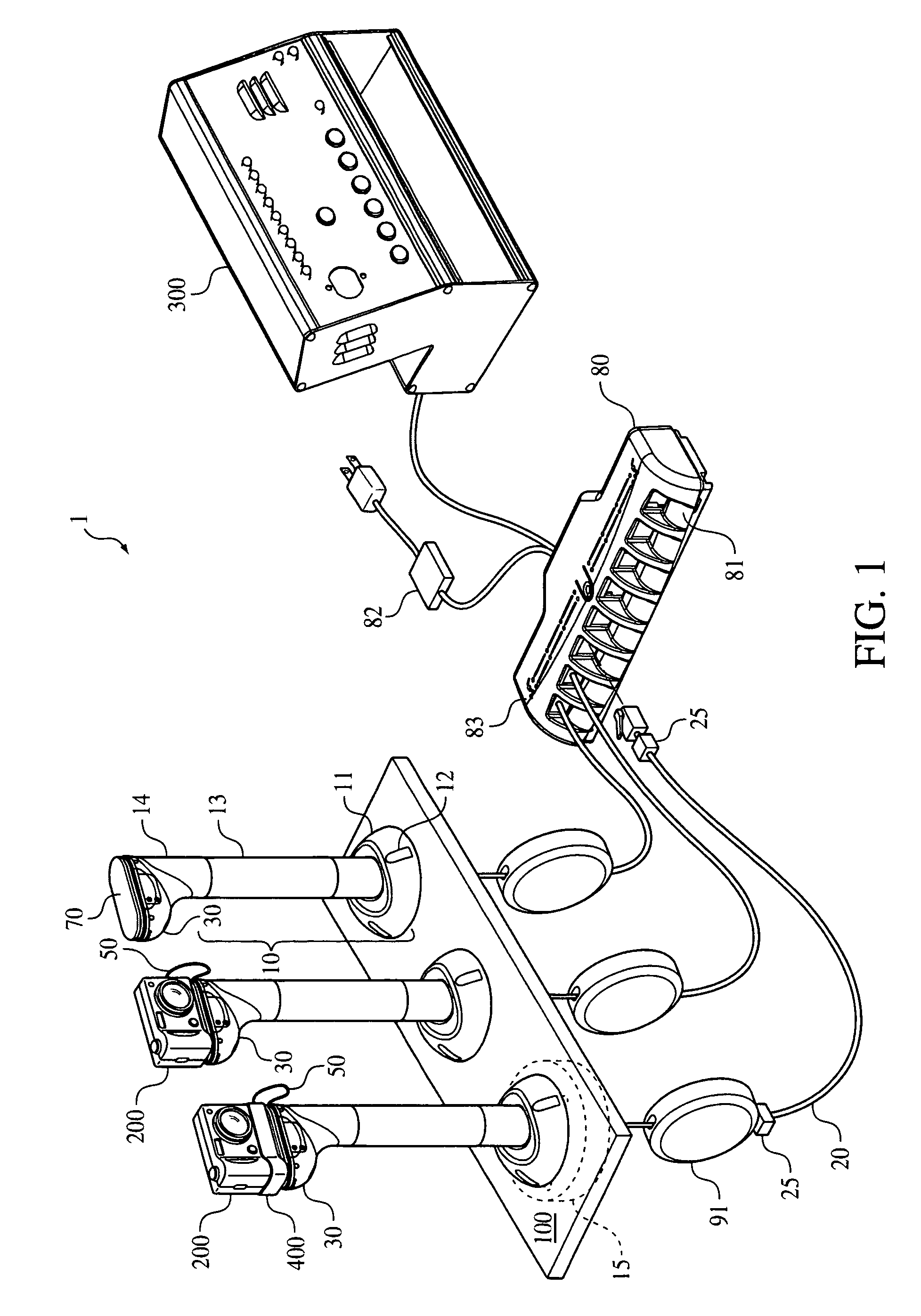
[0054]Referring now in detail to the drawings and, in particular, FIG. 1 shows a schematic view of a security system for displaying a handheld electronic device according to an embodiment of the invention. As shown in FIG. 1, security system 1 may include a stand assembly 10 which is mounted to a support 100, for example a display counter, tabletop or wall. Stand assembly 10 supports housing 30 and displayed handheld electronic device 200 and conceals a retractable cable 20 which is routed to housing 30.

[0055]Stand assembly 10 may be mounted to support 100 using a flange 15 positioned under support 100 and one or more fasteners, for example threaded fasteners or screws, which pass through notches provided in a base portion 11 of stand assembly 10. By using fasteners of appropriate lengths, the base 11 and flange 15 combination is adaptable to supports of various thicknesses. In this way stand assembly 10 is compatible with and may be mounted to a wide range of supports, for example ...


PUM


Abstract

A security system for powering and displaying a handheld electronic device includes a stand assembly mounted to a support and a housing removably mounted on a top portion of the stand assembly. The handheld electronic device is secured to a top portion of the housing and a sensor is coupled to the handheld electronic device. The sensor has a secure and a non-secure state and produces a detectable signal in the non-secure state. An output voltage controller controls an output voltage to the handheld electronic device which can be set only when the sensor is in the non-secure state. The output voltage is set to zero if the sensor is not placed in the secure state within a predetermined time.

Description

CROSS REFERENCE TO RELATED APPLICATIONS[0001]This application is a Continuation-in-Part of application Ser. No. 11 / 082,773, filed on Mar. 17, 2005 now U.S. Pat. No. 7,209,038, the disclosure of which is hereby incorporated by reference.BACKGROUND OF THE INVENTION[0002]1. Field of the Invention[0003]This invention relates to devices for securing and preventing unauthorized removal of displayed items. In particular, the invention relates to systems for displaying and securing handheld electronic devices wherein power may be provided to a displayed electronic device such that the device may be operated by a prospective purchaser.[0004]2. The Prior Art[0005]Handheld consumer electronic devices, for example digital cameras, camcorders, cellular phones, personal digital assistants, calculators and the like are preferably displayed in a manner such that prospective purchasers may handle and manipulate the device when contemplating a purchase. Certain handheld electronic devices, for exampl...

Claims


Application Information

Patent Timeline
Patent Type & Authority Patents(United States)
IPC IPC(8): G08B21/00
CPCG08B13/1409G08B13/1445
Inventor DECONINCK, JOSEPH F.AZZOLI, WILLIAM J.
Owner VANGUARD PRODS GROUP
Learn More