
Methods and apparatus for identifying candidate barcode fields

a barcode field and candidate technology, applied in the direction of instruments, visual presentation using printers, electromagnetic radiation sensing, etc., can solve the problems of lack of aiming capability, difficulty in using stationary scanners, and high cost of incorporating mechanical aiming features into stationary scanners, so as to alter the contrast of field and the brightness of field

Active Publication Date: 2008-02-05
SYMBOL TECH LLC
View PDF3 Cites 28 Cited by
  • Summary
  • Abstract
  • Description
  • Claims
  • Application Information

AI Technical Summary

Benefits of technology

The present invention is a barcode imaging system that allows an operator to select a specific barcode on an item by providing an image that highlights or identifies the barcode. The system analyzes the image to determine potential barcode fields and displays a modified image with the highlighted barcode field. The user can then initiate a decode session by touching the highlighted barcode field. The system can modify the image in various ways to make the barcode field easier to identify, such as adding an artificial reticule, scan line, or adjusting the contrast or brightness of the field. The technical effect of this invention is to improve the efficiency and accuracy of barcode identification in various settings.

Problems solved by technology

Furthermore, when it is inconvenient to place a barcode on the item itself, it is common to assemble a “pick sheet” of barcodes—i.e., a sheet of paper or the like upon which a large number of barcodes are assembled in row / column form.
It is very difficult to use a stationary scanner to select a particular barcode from among a number of barcodes present on a pick sheet or other item, as such scanners lack any form of aiming capability.
Incorporating a mechanical aiming feature into a stationary scanner is expensive and largely defeats the purpose of having a stationary scanner.

Method used


Image

  • Methods and apparatus for identifying candidate barcode fields
  • Methods and apparatus for identifying candidate barcode fields
  • Methods and apparatus for identifying candidate barcode fields

Examples


Embodiment Construction

[0016]The following detailed description is merely illustrative in nature and is not intended to limit the invention or the application and uses of the invention. Furthermore, there is no intention to be bound by any expressed or implied theory presented in the preceding technical field, background, brief summary or the following detailed description.

[0017]The invention may be described herein in terms of functional and / or logical block components and various processing steps. It should be appreciated that such block components may be realized by any number of hardware, software, and / or firmware components configured to perform the specified functions.

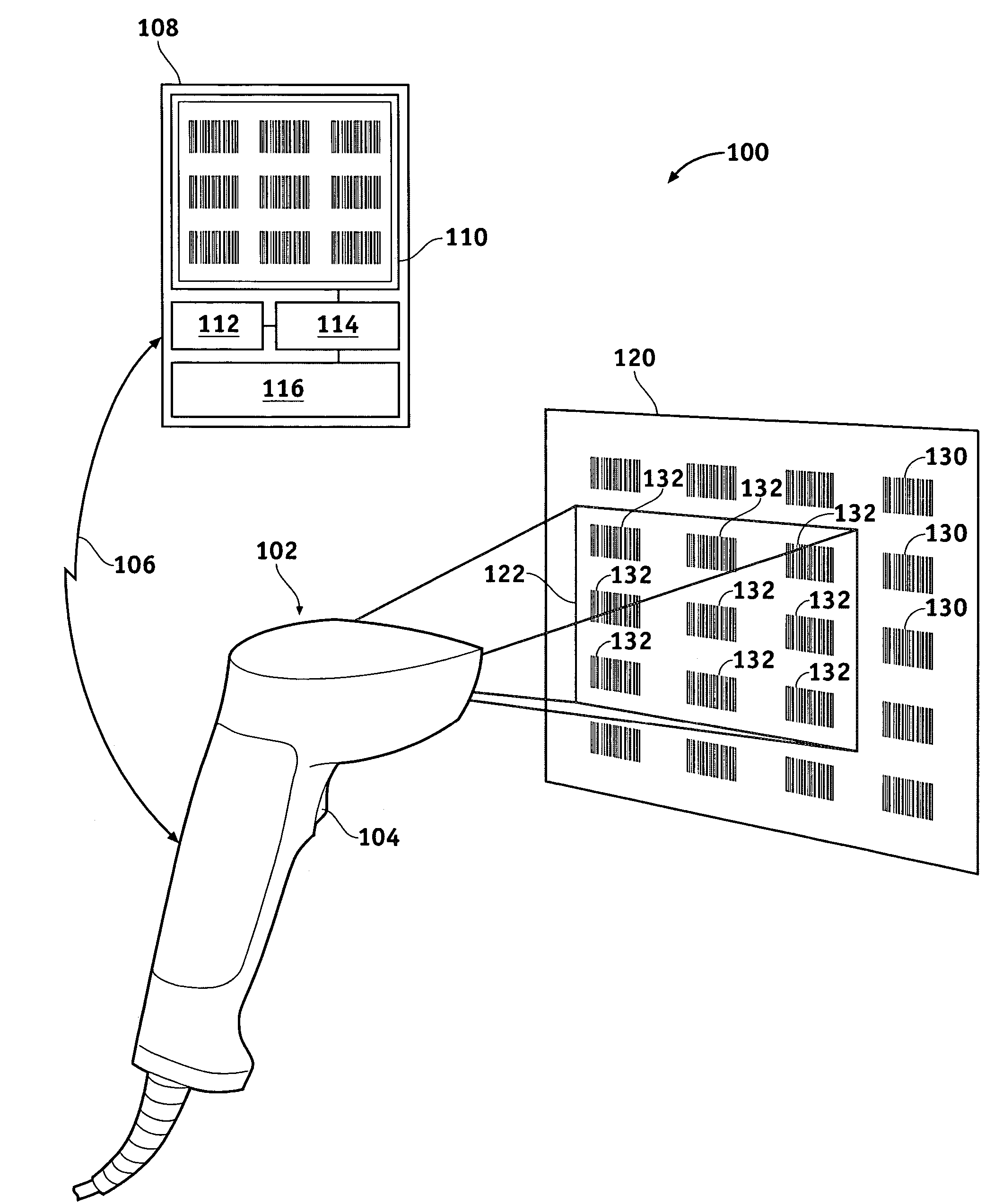
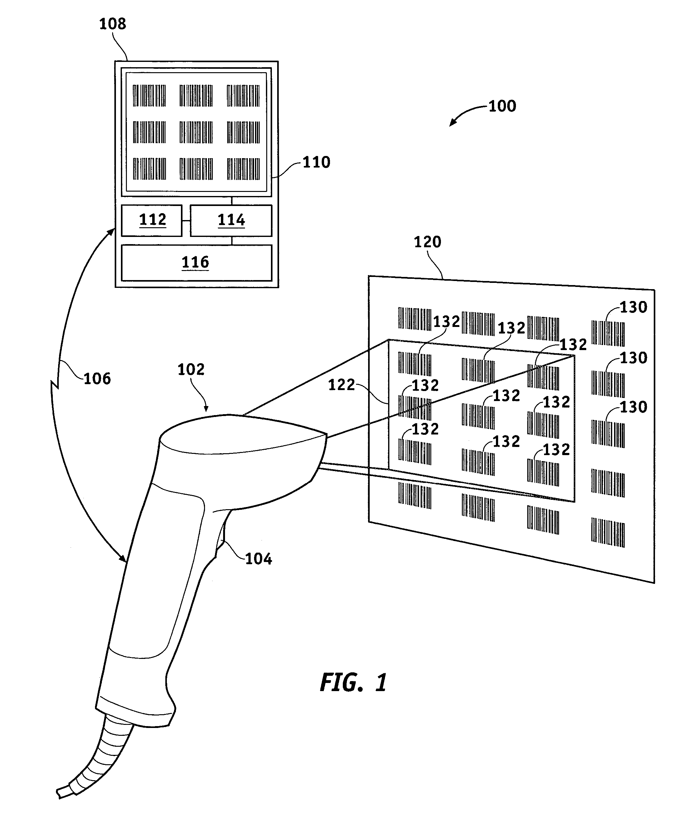
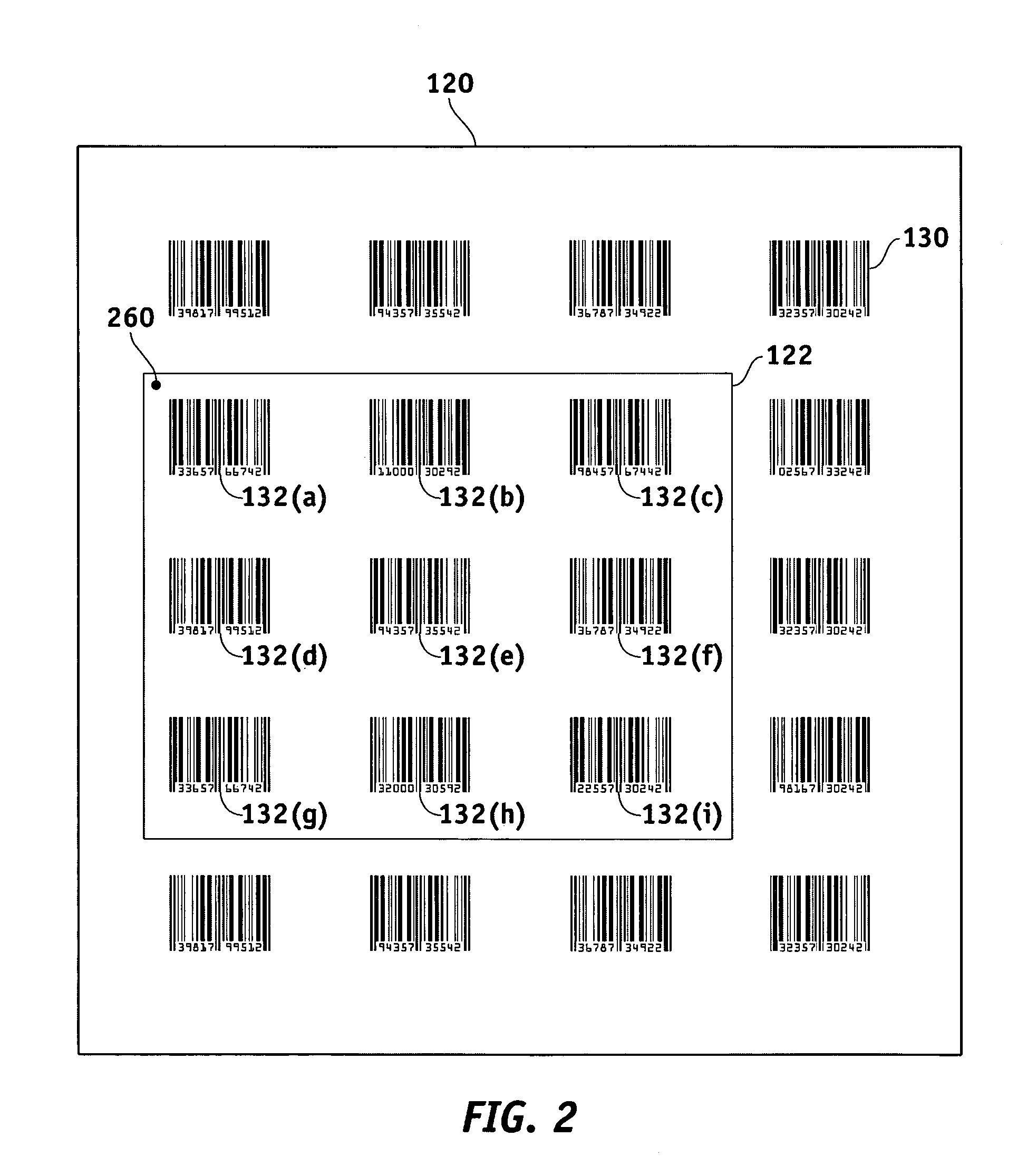
[0018]Referring to FIG. 1, an imaging system 100 generally includes a scanner (or “barcode reader”) 102, a terminal 108, and a communication link 106 between scanner 102 and terminal 108. Scanner 102 scans an area 122 of an item 120 within its field of view, wherein item 120 includes one or more visual indicia 130 (referred to herein, ...


PUM


Abstract

A system is provided for selecting a particular barcode on an item that includes multiple barcodes. The system (1) acquires, via a barcode imager, an image of the item within the field of view of the barcode imager, (2) analyzes the acquired image to determine a set of potential barcode fields, (3) determines, using a predetermined criterion (e.g., distance from center of imaged area, type of bar code, etc.), a candidate barcode field from among the set of potential barcode fields, (4) displays a modified image derived from the acquired image, wherein the candidate barcode field is identified within the modified image, and (5) allows the user to initiate a decode session when the candidate barcode field includes the desired barcode. The acquired may be modified to highlight the candidate barcode field in any number of ways, including, for example, superimposing an artificial reticule around the candidate field, superimposing an artificial scan line over the field, altering the contrast of the field, and / or altering the brightness of the field.

Description

TECHNICAL FIELD[0001]The present invention generally relates to barcode reading devices and, more particularly, to methods for selecting a target barcode from among a large number of barcodes printed on an item.BACKGROUND[0002]Barcode scanners and imagers are used to scan and decode visual indicia (e.g., “barcodes”) attached to products and the like. In many cases, an item or an item's packaging includes many different barcodes having any number of symbologies, giving rise to mixed-use requirements. Furthermore, when it is inconvenient to place a barcode on the item itself, it is common to assemble a “pick sheet” of barcodes—i.e., a sheet of paper or the like upon which a large number of barcodes are assembled in row / column form.[0003]While hand-held and portable scanners are easy to aim, and typically include some form of aiming aid, many scanners are stationary. A stationary scanner is one in which the scanning or imaging component is rigidly attached to a base or structure such t...

Claims


Application Information

Patent Timeline
Patent Type & Authority Patents(United States)
IPC IPC(8): G06K5/04
CPCG06K7/10712G06K7/10792G06K7/10871G06K7/1093G06K7/10861G06K2207/1011
Inventor EPSHTEYN, ALAN J.KOCH, DAVIDBOEHM, THOMAS F.LIVINGSTON, ALAN J.BORIOTTI, JOSEPH
Owner SYMBOL TECH LLC
Learn More