
Load tap change monitoring system and method

a monitoring system and technology of load taps, applied in the direction of automatic control, process and machine control, instruments, etc., can solve the problems of relative complexity and lack of applicability in retrofit situations

Inactive Publication Date: 2008-01-15
EATON INTELLIGENT POWER LIMITED
View PDF10 Cites 6 Cited by
  • Summary
  • Abstract
  • Description
  • Claims
  • Application Information

AI Technical Summary

Benefits of technology

[0010]The system and method of the invention substantially meet the aforementioned needs of the electric utility industry in providing a monitoring system that easily transmits load tap change data back to the transformer operator.

Problems solved by technology

A conventional electromechanical meter for displaying the tap position has drawbacks, such as producing only a local meter indication, which can be read by an operator only by going to the site of the meter.
The devices and methods shown in these patents all have various drawbacks, including relative complexity and lack of applicability in retrofit situations.

Method used


Image

  • Load tap change monitoring system and method
  • Load tap change monitoring system and method
  • Load tap change monitoring system and method

Examples


Embodiment Construction

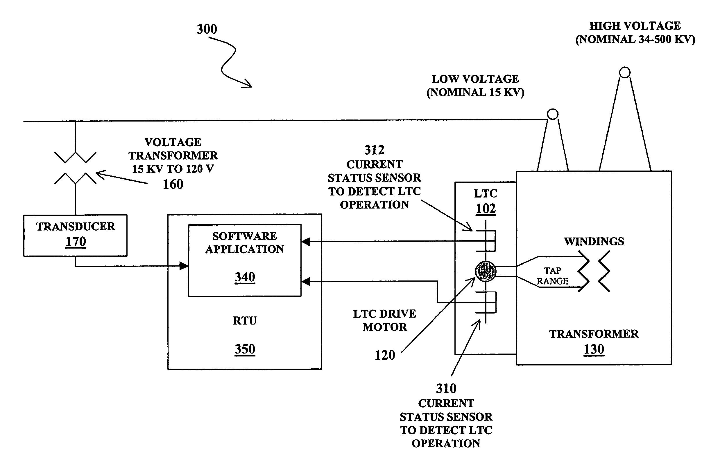
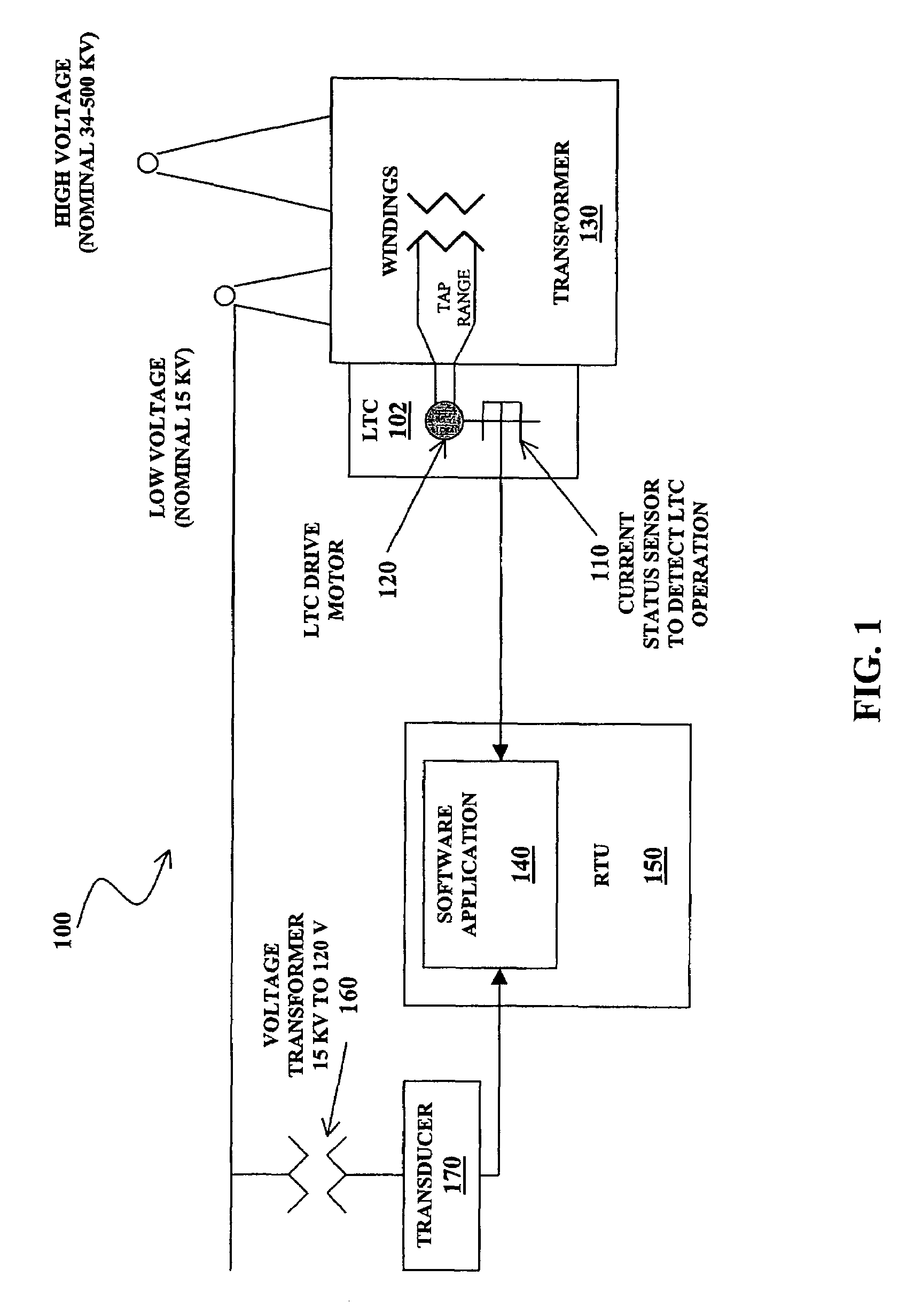
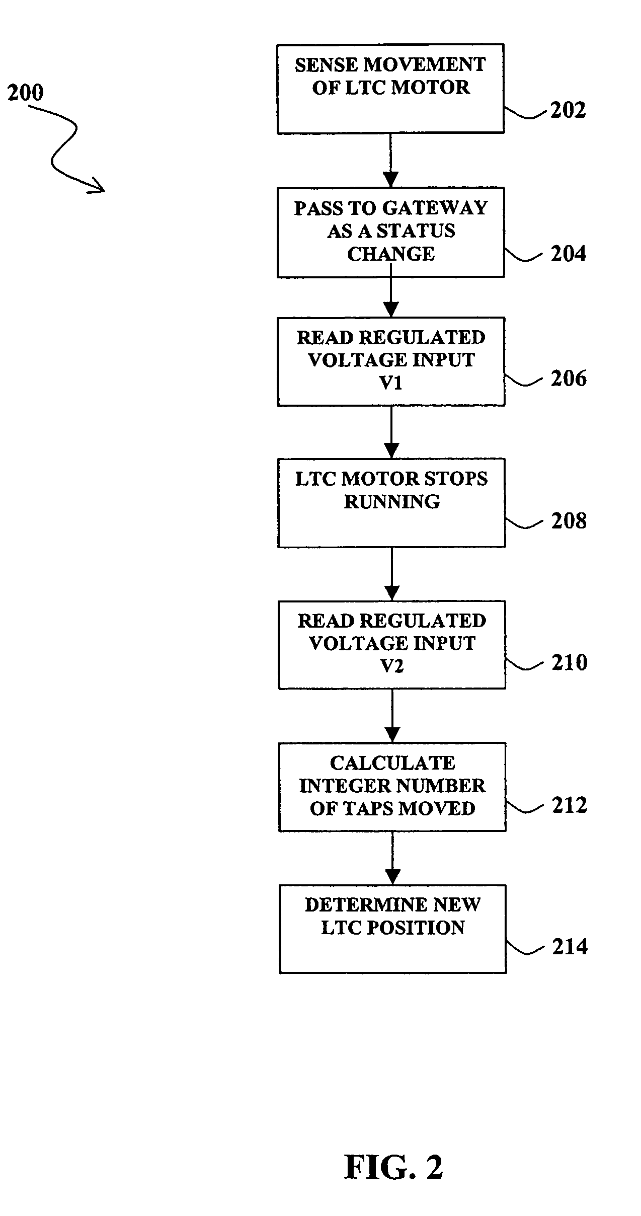
[0018]The invention is generally directed to a method and system for remotely tracking the position of load tap changing equipment that is used for voltage regulation on power transformer equipment. The invention can be more readily understood by reference to FIGS. 1-4 and the following description. While the invention is not necessarily limited to such an application, the invention will be better appreciated using a discussion of example embodiments in such a specific context.

[0019]In one embodiment illustrated by FIG. 1, a load tap changer monitoring system 100 includes a load tap changer (LTC) 102 and a hardware current status sensor 110. Sensor 110 is an ACST sensor, made by Cannon Technologies of Golden Valley, Minn., in one embodiment, or another similar and compatible sensor known to those skilled in the art, that is coupled to an LTC motor circuit 120 and a transformer 130. A custom remote terminal unit (RTU) software program 140, for example the Cannon SUBSTATION ADVISOR Sy...


PUM


Abstract

A system and method for remotely monitoring load tap changes on utility-type equipment are disclosed. In one example embodiment, a sensor measures a voltage before a tap change and compares the measured voltage to a voltage after the tap change. From this information, the direction of the tap change and the distance traveled can be determined. The system and method can also include a timer to measure an elapsed time required to complete a particular tap change and use this time information to determine the distance traveled. The direction of the tap change can be determined from a sensor that triggers the timer. The system and method thereby enable efficient and cost-effective remote monitoring of load tap changes and positions.

Description

RELATED APPLICATION[0001]This application claims the benefit of U.S. Provisional Application No. 60 / 523,770 filed Nov. 20, 2003, which is incorporated herein in its entirety by reference.TECHNICAL FIELD[0002]The invention generally relates to a system, software, and method for remotely monitoring load tap changes on utility-type transformer equipment.BACKGROUND OF THE INVENTION[0003]In service, a load tap changing transformer is supplied with an input voltage and produces an output voltage. The purpose of a tap changer is to produce an output voltage that is well-regulated or stable despite fluctuations in the input voltage and load. The load tap changer has a number of spaced-apart output terminals and performs its regulatory function by adjusting the tap position so that, for a given input voltage, the output is taken from whichever tap yields an output voltage closest to the target level. The number of taps provided depends on the environment in which the tap changer is designed ...

Claims


Application Information

Patent Timeline
Patent Type & Authority Patents(United States)
IPC IPC(8): G05F1/147H02J3/12
CPCG05F1/14H01H2009/0061
Inventor CANNON, MICHAELPETERSON, MARKPETERSON, AARON
Owner EATON INTELLIGENT POWER LIMITED
Learn More