
Personnel heating assembly

a technology of personnel and heating assembly, which is applied in the field of electric blankets, can solve the problems of unacceptable electromagnetic waves, unsuitable for such use, and unsatisfactory effects on patients

Active Publication Date: 2008-01-15
GRI ALLESET INC
View PDF29 Cites 25 Cited by
  • Summary
  • Abstract
  • Description
  • Claims
  • Application Information

AI Technical Summary

Benefits of technology

[0011]A disposable overcover for said electric blanket is impervious to liquid and encases the blanket, including electrical connectors and conductors, to avoid contamination of the blanket and thereby rendering the blanket usable for other patients merely by replacement of the overcover.

Problems solved by technology

Alternating current (AC) power sources or DC power sources with significant pulsations generate unacceptable electromagnetic waves and are accordingly not available for such use.
Ambient temperatures and body thermal control reactions vary throughout this process which affects the patient and is undesirable.

Method used


Image

  • Personnel heating assembly
  • Personnel heating assembly
  • Personnel heating assembly

Examples


Embodiment Construction

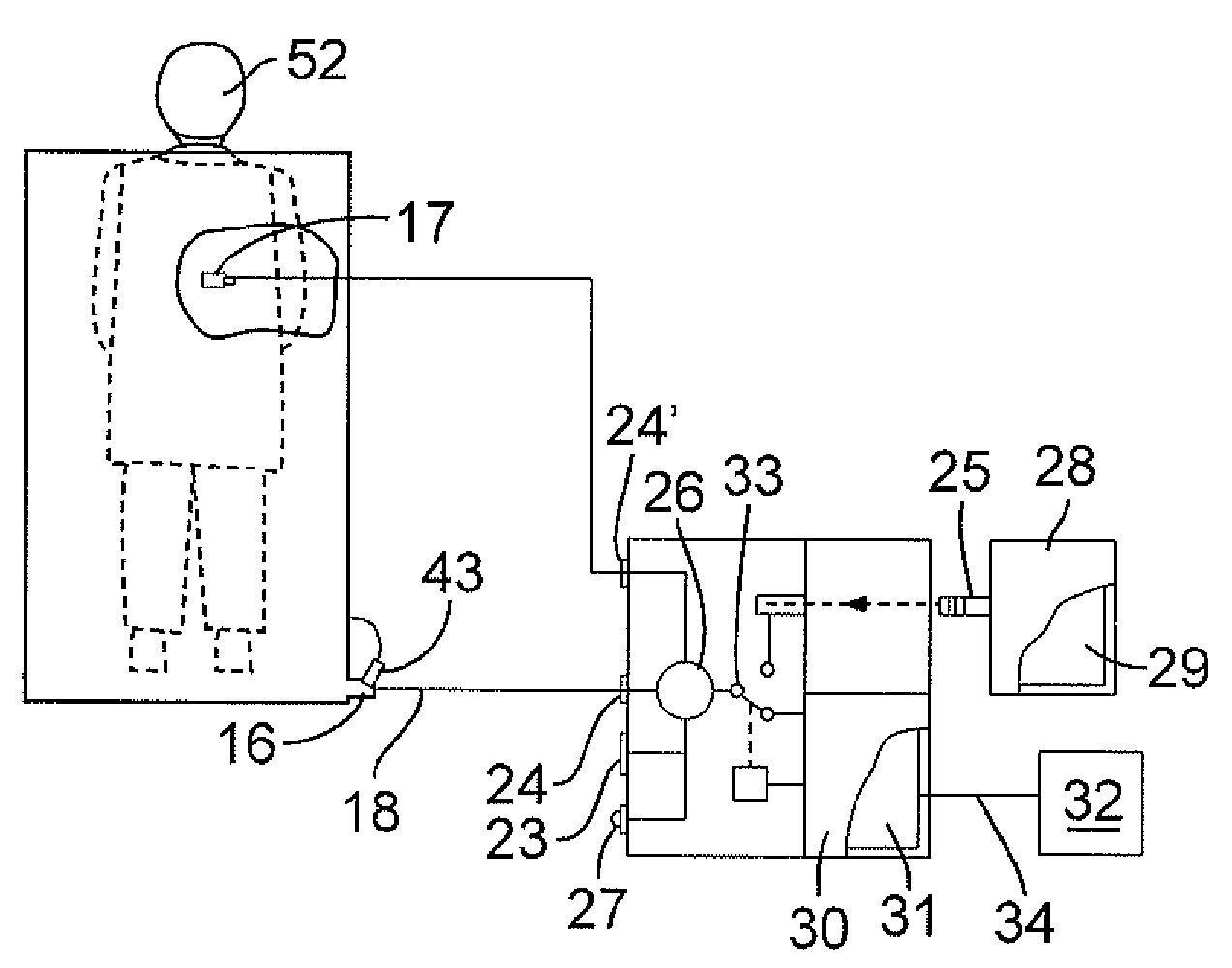
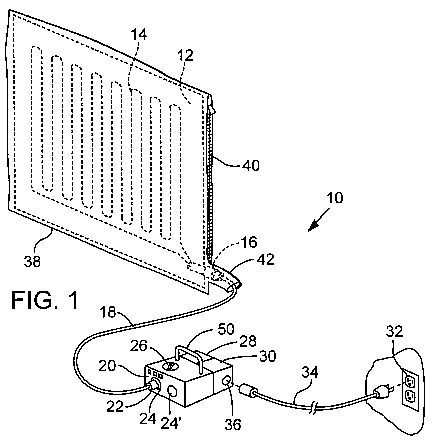
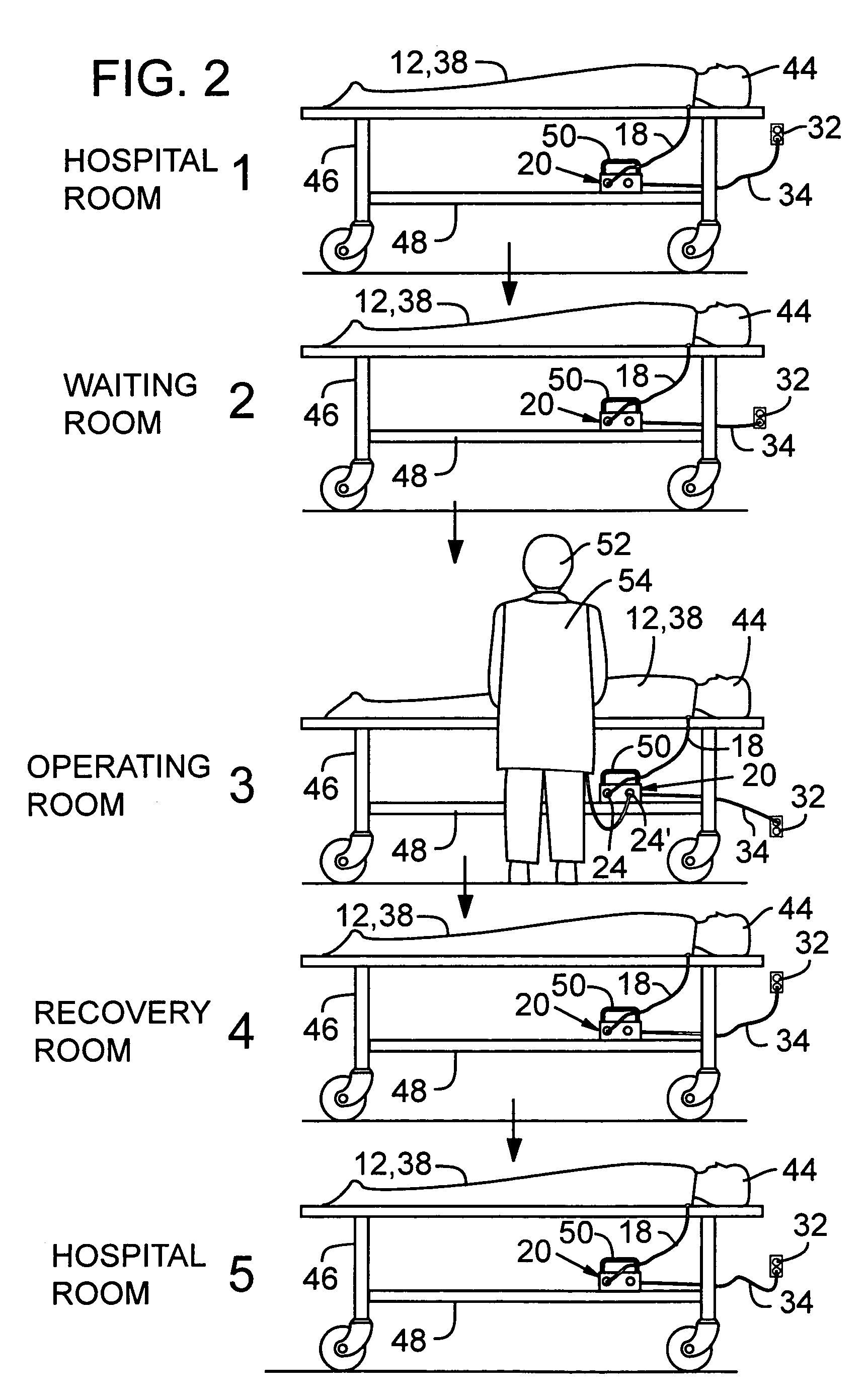
[0025]FIG. 1 and FIG. 7 illustrate an electric personnel warming assembly 10 in accordance with the present invention. The assembly includes a multi-layered blanket or cover portion 12 having direct current (DC) “heating circuitry”14 that is incorporated into the blanket. The blanket is desirably constructed of pliable cloth-like layers that include the desired insulation, heat reflection and heat conductive properties to ideally promote inwardly directed heat conveyance to a patient covered by the blanket. Note FIG. 7 which illustrates an outer layer 13 (having outer side 13a and inner side 13b) and an inner layer 15 (having inner side 15b and outer side 15a) with heating circuitry 14 sandwiched there between. Layer 13 is substantially heat reflective / non-conductive, and layer 15 is heat conductive. (See also commonly owned U.S. Pat. No. 5,986,243 incorporated herein by reference). A connector 16 and wire conductor 18 connect the heating circuitry 14 to a control apparatus 20 via a...


PUM


Abstract

A heating assembly, is disclosed which includes a blanket portion and a control apparatus for electrically heating the blanket portion. The control apparatus generates direct current power of desired wave form to enable the assembly to be used for warming patients without interference of medical equipment as may be used in the process of a surgery. Alternate power sources include battery power and alternating current power transformed by a transformer into direct current power.

Description

RELATED APPLICATION[0001]This application is a non-provisional application claiming benefit under 35 U.S.C. § 119(e) of U.S. Provisional Application No. 60 / 401,006, filed Aug. 5, 2002.BACKGROUND OF THE INVENTION[0002]1. Field of the Invention[0003]This invention relates to an electric blanket that operates on DC power and can accordingly be battery operated to enable users to operate the heating elements of the blanket where AC power is not available, e.g. golf cart or medical EMT use, or otherwise where AC power is not desirable, e.g., for warming patients in an environment where power cords or electromagnetic waves from alternating current sources may be detrimental.[0004]2. Background Information[0005]Battery powered electric blankets are not new, as illustrated in the commonly owned U.S. Pat. No. 5,986,243, the disclosure of which is incorporated herein by reference. Whereas the electric blanket of the '243 patent was primarily targeted as a stadium blanket, a secondary use that...

Claims


Application Information

Patent Timeline
Patent Type & Authority Patents(United States)
IPC IPC(8): H05B3/34H05B1/02
CPCH05B1/0272H05B3/342H05B2203/003
Inventor CAMPF, MELVIN F.THORNE, JIMHOMOYOUN, HABIBFIELDS, R. WAYNE
Owner GRI ALLESET INC
Learn More