
Responding to changes in measurement of system load in spread spectrum communication systems

a communication system and spread spectrum technology, applied in the field of wireless communication, can solve problems such as undesired interference fluctuations at the receiving end, sudden increases or changes in load measurement, and transmission monitoring

Inactive Publication Date: 2008-01-08
LUCENT TECH INC
View PDF5 Cites 60 Cited by
  • Summary
  • Abstract
  • Description
  • Claims
  • Application Information

AI Technical Summary

Problems solved by technology

Likewise, the sudden increases or changes in the load measurement may be caused by variations of the CDMA system load, e.g., due to a handover or user activity.
However, one problem of interference measurements is their sensitivity to interference fluctuations, which may occur due to many different reasons including interference from a CDMA system, interference from other mobile systems, and external interference.
Specifically, the interference from a CDMA system involves a known source of fluctuations, e.g., a mobile user itself.
Therefore, for a certain period, a wireless communication device, such as a mobile station transmits with a higher power, causing undesired interference fluctuations at a receiving end, e.g., at a base station, such as a Node B in an uplink.
Adjacent channel interference from mobile communication systems at adjacent frequency bands may cause additional interference.
While an adjacent CDMA system may likely cause only a general increase in background noise, time division multiple access (TDMA) systems like Global System of Mobile Communications (GSM) may be a source of substantial fluctuating interference.
External interference may cause fluctuations that may not be originated from any mobile user.
For example, significant broadband pulses may result due to other types of noise, such as created by an electrical self-starter of a car, power lines, heavy current switches, arc welders, fluorescent lights, and the like.
Because of the occurrence of the high spikes, a typical load control algorithm causes a typical congestion control to drop existing calls.
Such dropping of calls is indeed an undesired outcome of load control given the relatively short duration of these spikes, e.g., in a range of a few 100 milliseconds (msecs).
Application of high filtering periods will significantly slow the reaction of UL load control during a sudden load increase / decrease.
Hence, load control will not be able to react fast enough on such changes by appropriately enabling / disabling the blocking / dropping of calls.
Similar to higher filtering periods, the increased time-to-trigger will make load control reaction too slow on the load changes.
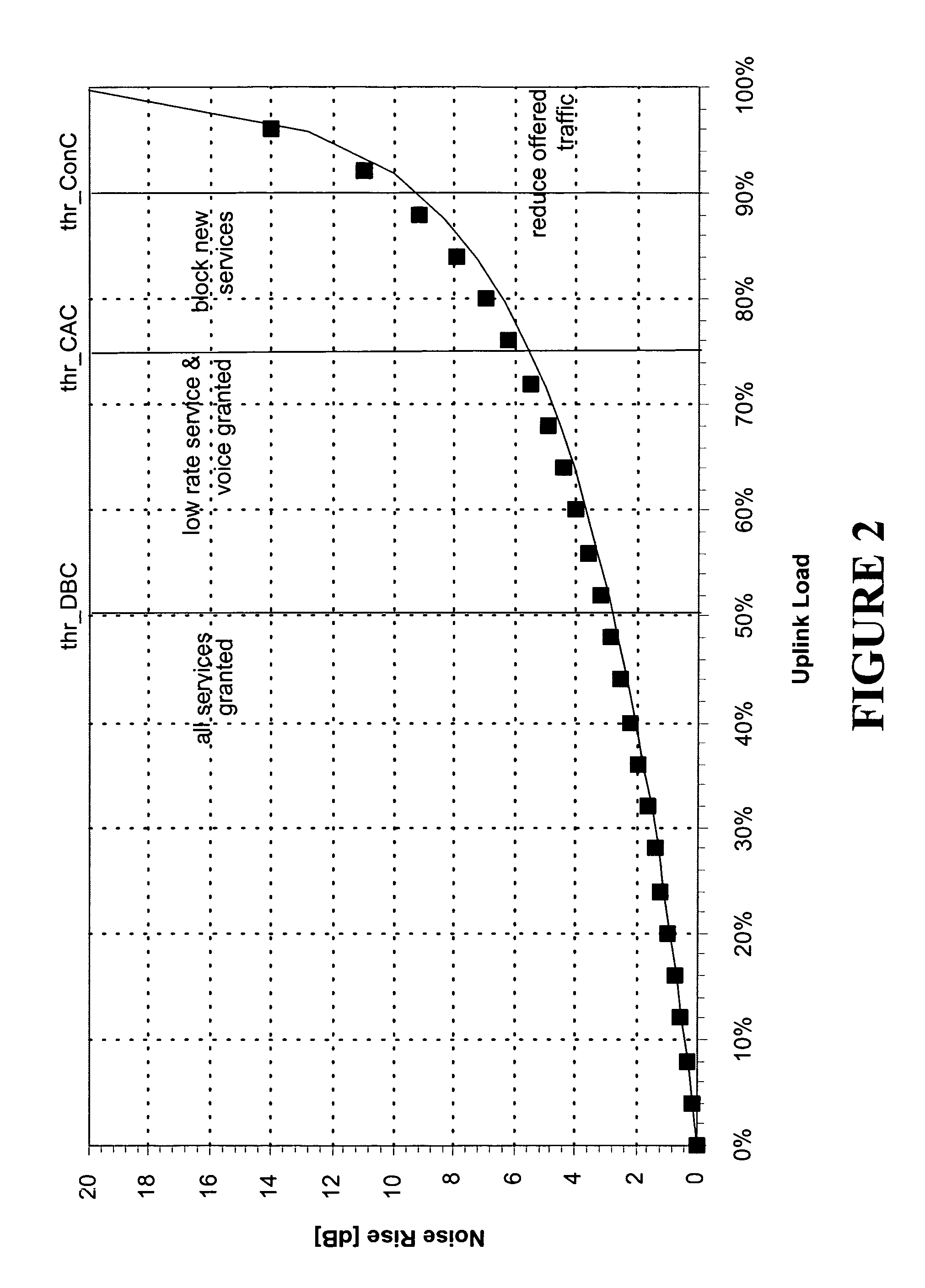
The usage of higher thresholds is risky since same CDMA systems become unstable in a loading region around and above 90%, as shown in FIG. 2.
In such a high load condition, the transmit power control essentially functions inadequately, which leads to a much higher risk of dropping ongoing calls due to bad radio frequency (RF) link conditions.
Accordingly, the drawbacks set forth above may result in imprecise measurements of system load in a CDMA system.
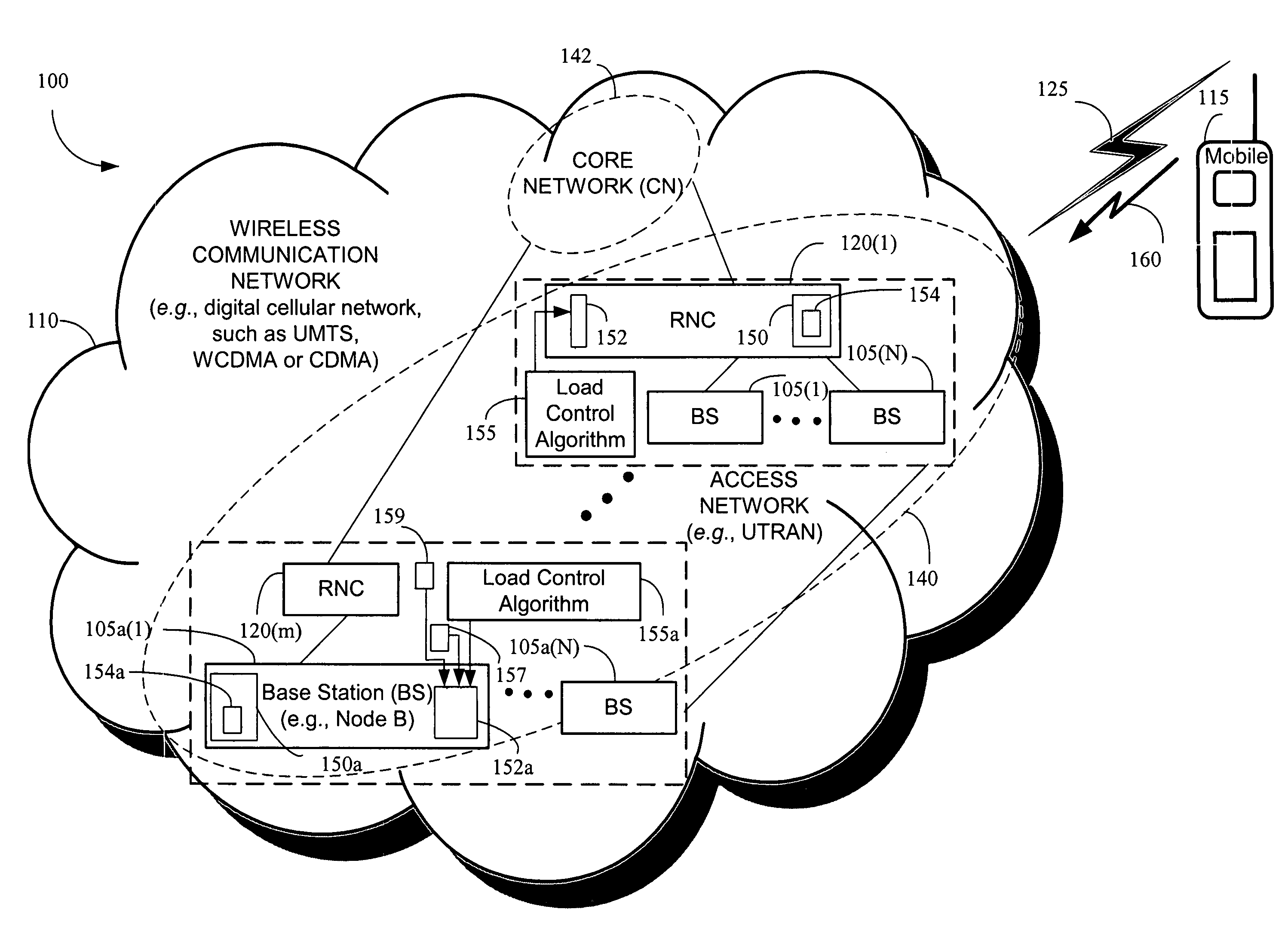
That is, an inaccurate estimate and control of an uplink load may lead to inefficient resource management in many UMTS standard based products including the Node B base stations and UTRAN access networks.

Method used


Image

  • Responding to changes in measurement of system load in spread spectrum communication systems
  • Responding to changes in measurement of system load in spread spectrum communication systems
  • Responding to changes in measurement of system load in spread spectrum communication systems

Examples


Embodiment Construction

[0032]Illustrative embodiments of the invention are described below. In the interest of clarity, not all features of an actual implementation are described in this specification. It will of course be appreciated that in the development of any such actual embodiment, numerous implementation-specific decisions may be made to achieve the developers' specific goals, such as compliance with system-related and business-related constraints, which will vary from one implementation to another. Moreover, it should be appreciated that such a development effort might be complex and time-consuming, but may nevertheless be a routine undertaking for those of ordinary skill in the art having the benefit of this disclosure.

[0033]Generally, a method and apparatus are provided for responding to a change in measurement of a system load in a spread spectrum communication system. Using a load control algorithm, for example, a CDMA system based on the UMTS may efficiently handle sudden changes or variatio...


PUM


Abstract

The present invention provides a method and an apparatus for responding to changes in measurement of a system load in a spread spectrum communication system. Using a load control algorithm, for example, the spread spectrum communication system may handle sudden changes or variations, such as spikes or steps in system load measurements for an uplink and / or a downlink between a mobile unit and an access network. The load control algorithm determines whether a sudden variation of a measured system load is generated by a source not under a power control or is caused by a variation of a spread spectrum communication system load. A load control measure may be selectively applied to adjust one or more parameters associated with the system load. That is, an increase of a first new measurement value may be limited to a given maximum increment for one sampling time period of a plurality of sampling time periods in response to a spike in the system load or a desired response to a sudden increase of the system load may be delayed by a given maximum number of measurement samples. By allowing a limited increase, the response of the spread spectrum communication system to sudden changes of a system load may be controlled such that some blocking may occur but dropping of calls may be avoided. In this manner, the load control algorithm may avoid unnecessary dropping of calls.

Description

BACKGROUND OF THE INVENTION[0001]1. Field of the Invention[0002]This invention relates generally to telecommunications, and more particularly, to wireless communications.[0003]2. Description of the Related Art[0004]Mobile communication systems are increasingly being utilized to transfer information, such as data, voice, text or video, among communication devices on a wireless network. To this end, a number of standards for network technologies and communication protocols have been proposed or suggested, rendering a variety of services to users. For example, third generation partnership project (3GPP) standardization has been introduced to provide IP based multimedia services to users based on the Universal Mobile Telecommunications System (UMTS) standard in a radio access network, such as a UMTS Terrestrial Radio Access Network (UTRAN).[0005]A wireless communications system, for instance, a spread spectrum wireless communications system, such as code division multiple access (CDMA) ...

Claims


Application Information

Patent Timeline
Patent Type & Authority Patents(United States)
IPC IPC(8): H04Q7/20H04W52/34
CPCH04B17/20H04W52/343
Inventor MUECKENHEIM, JENSSAPIANO, PHILIP CHARLESLIM, SEAU SIAN
Owner LUCENT TECH INC
Learn More