
Pneumatic launcher system and method for operating same

Inactive Publication Date: 2008-01-01
THE UNITED STATES OF AMERICA AS REPRESENTED BY THE SECRETARY OF THE NAVY
View PDF14 Cites 16 Cited by
  • Summary
  • Abstract
  • Description
  • Claims
  • Application Information

AI Technical Summary

Benefits of technology

[0008]It is another object of the present invention to provide a launcher apparatus that is inexpensive to manufacture, implement and maintain.

Problems solved by technology

Next, the intermediate chamber is then depressurizing to produce a pressure imbalance between the plenum and intermediate chambers that causes said aft and forward rupture disks to rupture.

Method used


Image

  • Pneumatic launcher system and method for operating same
  • Pneumatic launcher system and method for operating same
  • Pneumatic launcher system and method for operating same

Examples


Embodiment Construction

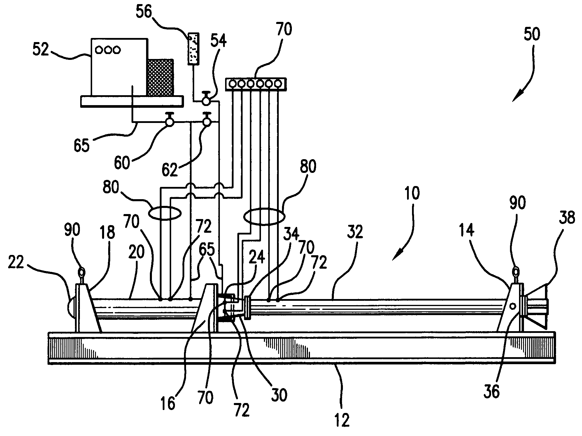
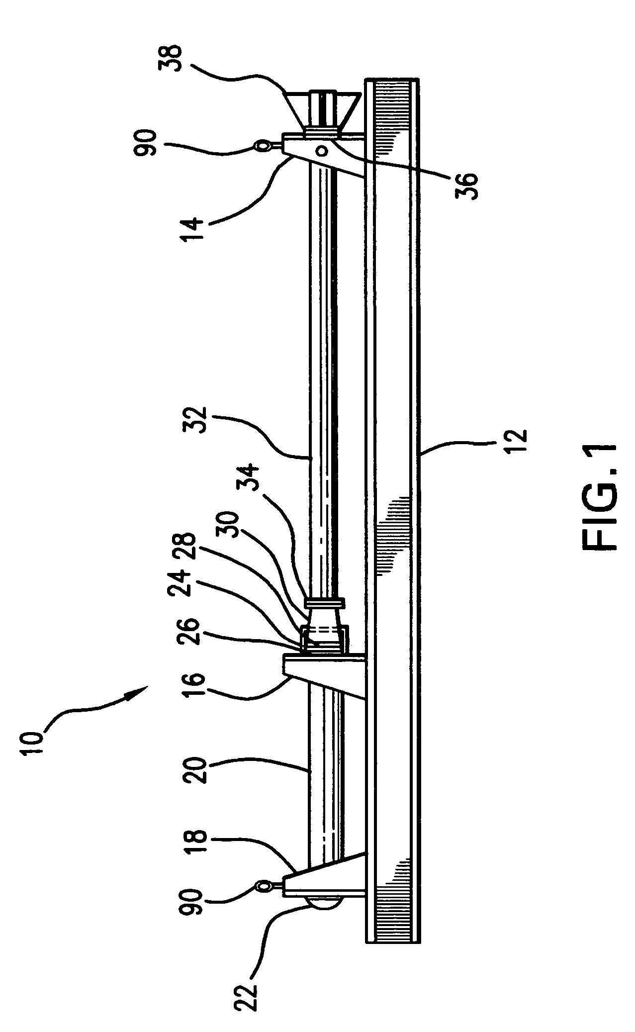
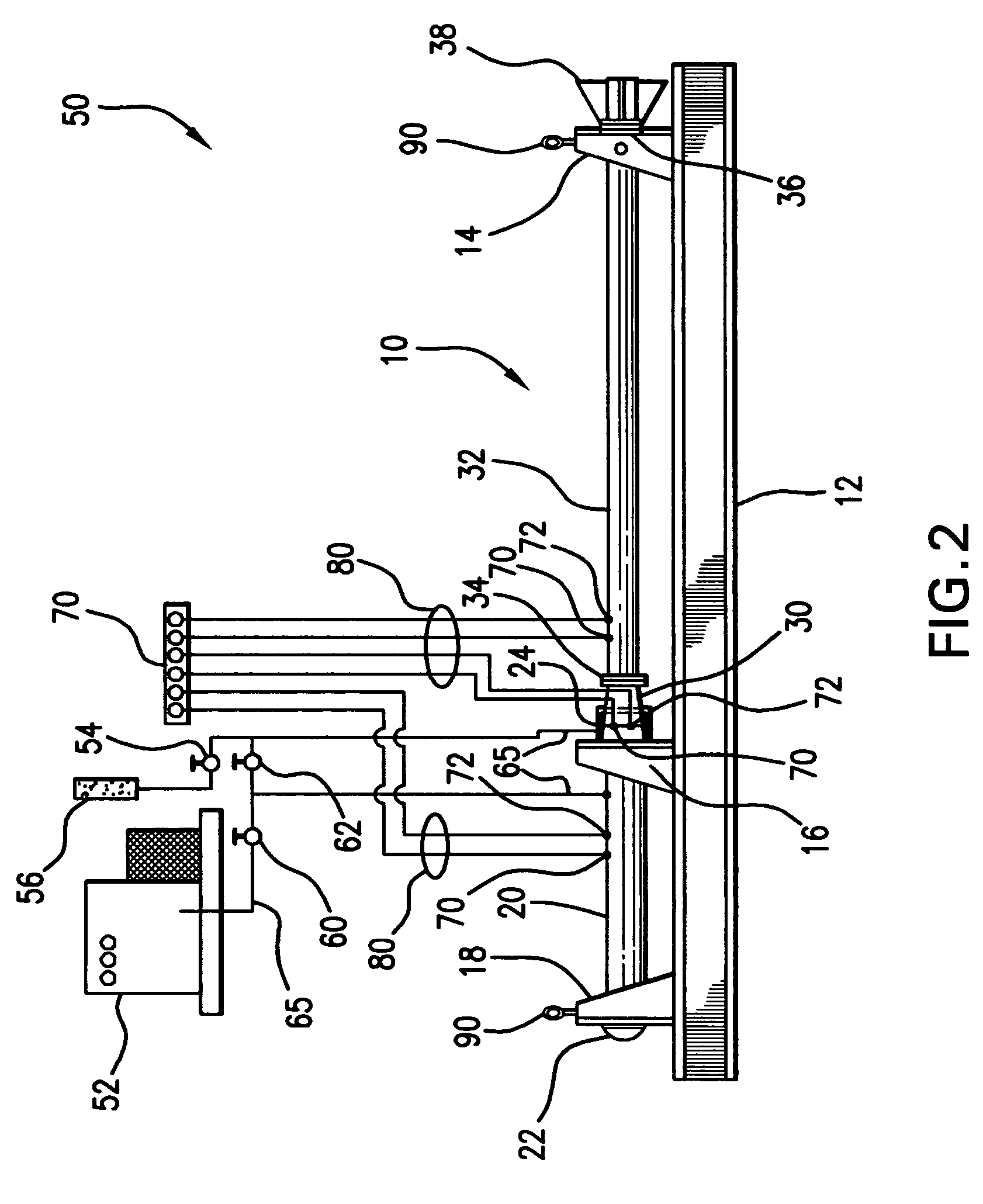
[0015]Referring to FIG. 1, there is shown pneumatic launcher 10 in accordance with the invention. Pneumatic launcher 10 is to be used to launch supercavitating vehicles or other projectiles. As used herein, the term “projectiles” shall include supercavitating vehicles, torpedoes, sonar buoys, and other similar objects. Pneumatic launcher 10 comprises support base member 12, forward support 14, middle support 16 and aft support 18. Pneumatic launcher 10 further comprises plenum chamber 20 which is supported by middle support 16 and aft support 18. In a preferred embodiment, plenum chamber 20 is attached to middle support 16 and aft support 18. Plenum chamber 18 includes end cap 22. Pneumatic launcher 10 further comprises intermediate chamber 24 that is formed by aft rupture disk 26 and forward rupture disk 28 which are arranged in series. Pneumatic launcher 10 further includes contraction member 30, the purpose of which is described in the ensuing description. Aft rupture disk 26 and...


PUM


Abstract

A pneumatic launcher has a plenum chamber section, an intermediate chamber section and a launch tube section connected together in a generally linear arrangement. The plenum chamber section defines a plenum chamber that has a closed end and an open end. The intermediate chamber section has aft and forward rupture disks consecutively arranged to define an intermediate chamber. The plenum chamber is pressurized with a pressurized gas to a design plenum pressure and the intermediate chamber is pressurized with a pressurized gas to pressure that is about one-half the design plenum pressure. The intermediate chamber is then depressurizing to produce a pressure imbalance between the plenum and intermediate chambers that causes said aft and forward rupture disks to rupture. As a result, pressure equilibrium occurs between the plenum chamber and launch tube thereby discharging the fluid and projectile from the interior of the launch tube.

Description

STATEMENT OF GOVERNMENT INTEREST[0001]The invention described herein may be manufactured and used by or for the Government of the United States of America for governmental purposes without the payment of any royalties thereon or therefor.BACKGROUND OF THE INVENTION[0002]1. Field of the Invention[0003]The present invention generally relates to a pneumatic launcher apparatus.[0004]2. Description of the Prior Art[0005]Supercavitating underwater vehicles and projectiles are known in the art. One such supercavitating underwater projectile is described in Harkins et al. U.S. Pat. No. 5,955,698. Typically, such supercavitating underwater vehicles and projectiles are launched by a launcher system. The launcher for a supercavitating vehicle must meet several important requirements. Specifically, the launcher must achieve the necessary exit velocity for the selected vehicle or projectile design. The launcher must be of an economically efficient design. Preferably, the launcher should utilize ...

Claims


Application Information

Patent Timeline
IPC IPC(8): F41C9/06F41A23/00F41B11/00
CPCF41A23/02F41B11/83F42B19/00
Inventor GIESEKE, THOMAS J.BITSAKIS, NICHOLASGAUTHIER, BENOIT G.KUKLINSKI, ROBERT
Owner THE UNITED STATES OF AMERICA AS REPRESENTED BY THE SECRETARY OF THE NAVY
Learn More