
Drive arrangement for the drive of attached implements for a vehicle

a technology for driving arrangements and implements, which is applied in the direction of hybrid vehicles, gearing, agricultural machines, etc., can solve the problems of high cost and high cos

Inactive Publication Date: 2007-12-25
DEERE & CO
View PDF22 Cites 30 Cited by
  • Summary
  • Abstract
  • Description
  • Claims
  • Application Information

AI Technical Summary

Benefits of technology

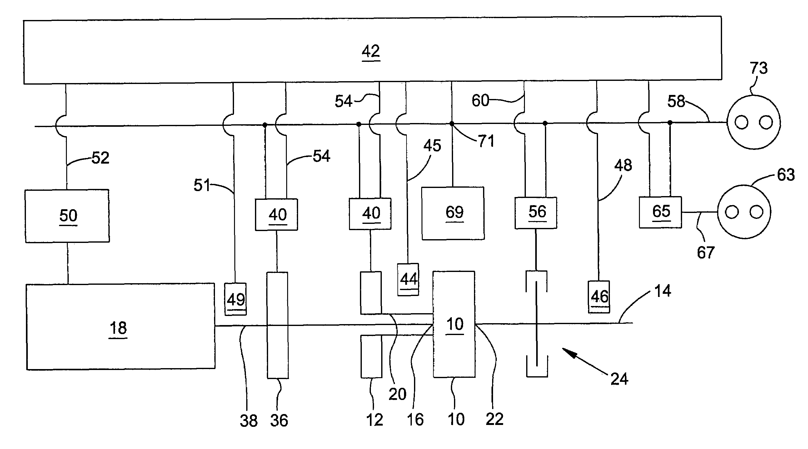
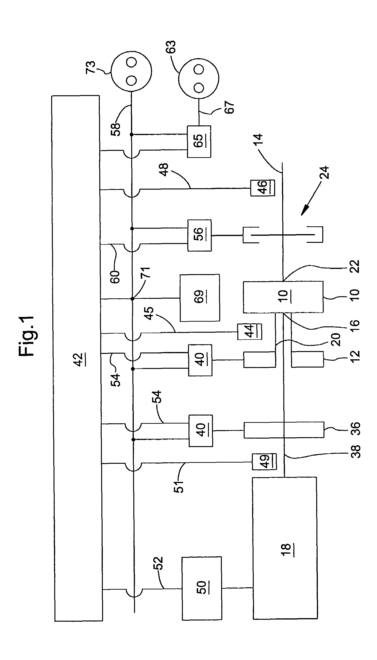
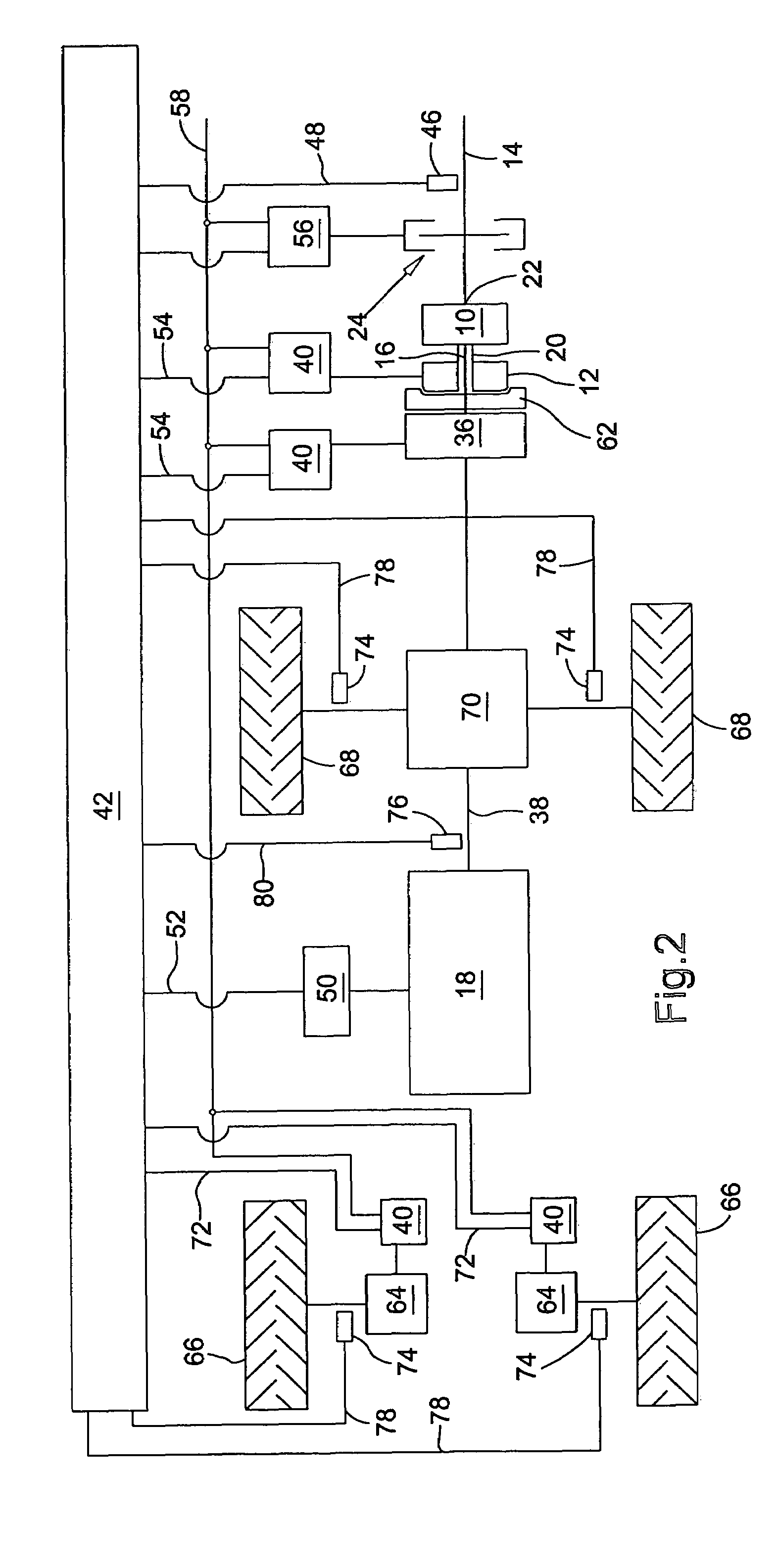
The invention is a drive arrangement that allows for a constant speed of operation for an attached implement, regardless of changes in the engine speed. This is achieved through the use of an electrical machine that controls the speed of the power take-off shaft, which is connected to the gearbox. This arrangement eliminates the need for an infinite gearbox in the vehicle's driveline, and allows for greater flexibility in vehicle speed and engine speed.

Problems solved by technology

The technical problem addressed in this patent text is the need for a drive arrangement for attached implements on an agricultural utility vehicle that allows for a constant power take-off shaft rotational speed despite a varying rotational speed of the internal combustion engine. This is important for ensuring the proper operation of the attached implement and avoiding any irregular planting intervals.

Method used


Image

  • Drive arrangement for the drive of attached implements for a vehicle
  • Drive arrangement for the drive of attached implements for a vehicle
  • Drive arrangement for the drive of attached implements for a vehicle

Examples


first embodiment

[0057]FIG. 4 shows a further development of the first embodiment according to FIG. 1, that is provided with a spur gear stage 82 which can be shifted. A shaft 84 is provided between the spur gear stage 82 and the third gearbox interface 22, which transmits the torque made available by the third gearbox interface 22 to the spur gear stage 82 that can be shifted. The spur gear stage 82 that can be shifted includes two spur gears 86 connected to the shaft 84, where the spur gear 86 shown at left is provided with a larger diameter compared to the spur gear 86 shown at right. Each of the spur gears 86 mesh with a shifted spur gear 88, where the spur gear 88 shown at left is provided with a smaller diameter than the spur gear 88 shown at right.

second embodiment

[0058]The shifted spur gears 88 can be shifted in corresponding manner by a control arrangement 90, so that the torque transmitted by the shaft 84 is transmitted to the power take-off shaft 14 either over the two spur gears 86, 88 shown at left or the two spur gears 86, 88 shown at right. The control arrangement 90 is controlled by the control arrangement 94 by means of the control arrangement 42 over the connecting line 92. The shifted spur gear stage 82 of FIG. 4 can also be connected with the power take-off shaft 14 of the second embodiment according to FIG. 2.


PUM


Abstract

The present invention concerns a drive arrangement for the drive of attached implements for a vehicle, particularly an agricultural or industrial utility vehicle, with a combination gearbox, an electrical machine and a power take-off shaft, where a gearbox interface of the combination gearbox can be driven by an internal combustion engine and where the electrical machine is connected with a second gearbox interface of the combination gearbox. In order to make available a variable power take-off shaft rotational speed that is independent of the rotational speed of the internal combustion engine, the drive arrangement according to the invention is characterized by the fact that the power take-off shaft is connected with a third gearbox interface of the combination gearbox. Furthermore the present invention concerns a vehicle with such a drive arrangement.

Description


Claims


Application Information

Patent Timeline
Owner DEERE & CO
Learn More