
Automatic door opener with magnetic clutch

a door opener and magnetic technology, applied in the direction of mechanical actuator clutches, mechanical accessories, mechanical apparatuses, etc., can solve the problems of slipping upon a definite overload, great torsional capacity, and inability to move easily

Inactive Publication Date: 2007-12-25
POWER ACCESS
View PDF29 Cites 41 Cited by
  • Summary
  • Abstract
  • Description
  • Claims
  • Application Information

AI Technical Summary

Benefits of technology

"The present invention relates to a motorized door opener mechanism and a self-contained clutch. The mechanism includes a motor with a drive shaft and an opener arm with an opener hub rotatably mounted on the drive shaft. There is a drive plate fixedly mounted on the drive shaft for rotation therewith, with the drive plate comprising a magnetically attractable material. An electromagnet is positioned to engage the opener hub with the drive plate. The clutch includes a hub with an annular drive plate and a clutch post of reduced diameter relative to the drive plate, pressure means for generating friction to engage the rotatable member with the drive plate for rotation therewith, and a retaining cap to secure at least the hub of the rotatable member and the pressure means on the clutch post. The mechanism may also include a drag brake. The technical effects of this invention include improved efficiency and reliability of the motorized door opener mechanism."

Problems solved by technology

While such door openers typically have some form of clutch mechanism, the weight of the garage door and the necessity that the garage door be raised vertically on rails require a slip clutch of great torsional capacity and some switching mechanism to stop the motor or interrupt the drive train when the door encounters an obstacle.
In operation, the door will move under normal operating conditions but may slip upon a definite overload.
These devices suffer from the drawback that upon loss of power the door is not easily movable, creating a hazard in the event of a fire.

Method used


Image

  • Automatic door opener with magnetic clutch
  • Automatic door opener with magnetic clutch
  • Automatic door opener with magnetic clutch

Examples


Embodiment Construction

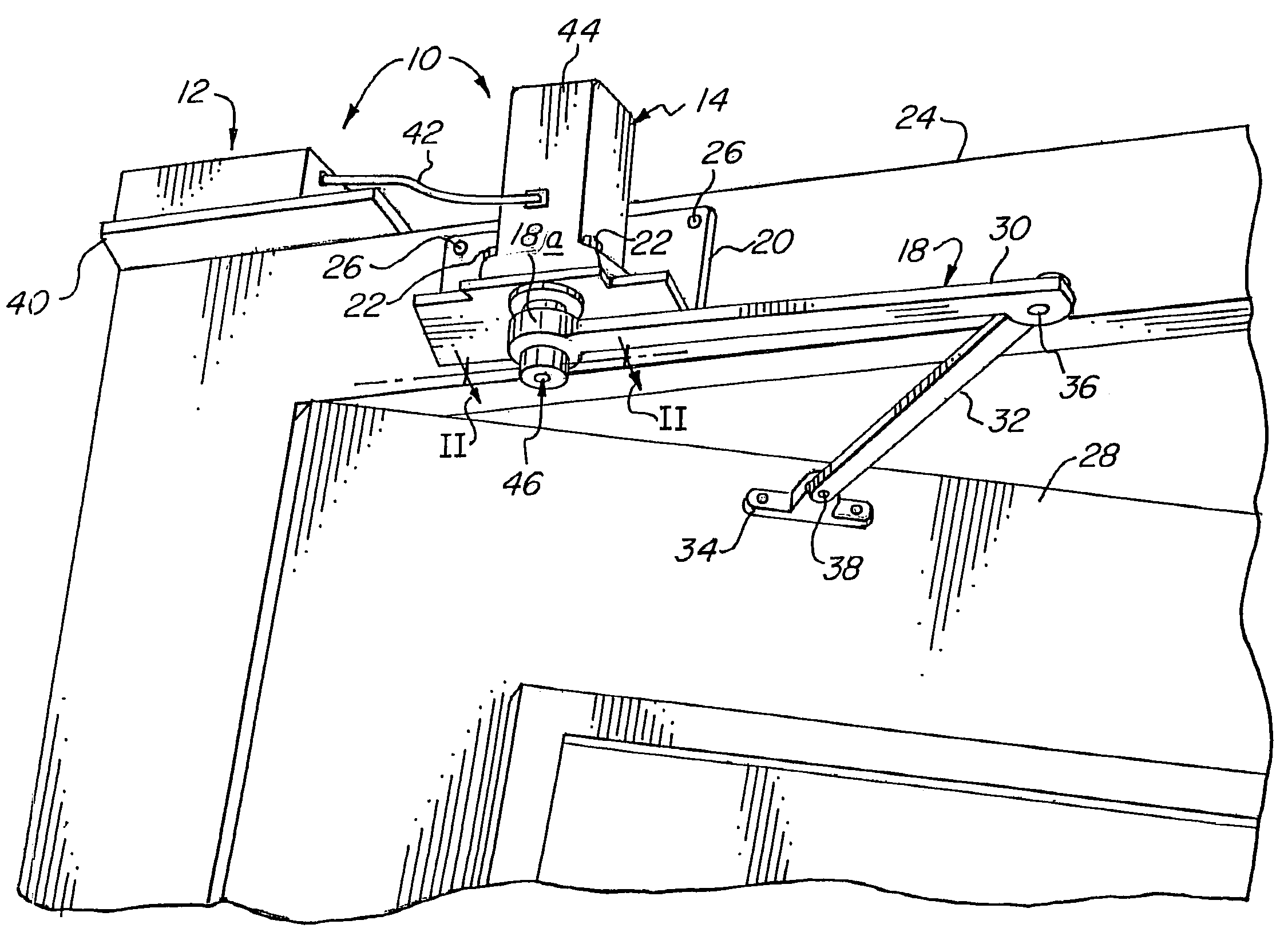
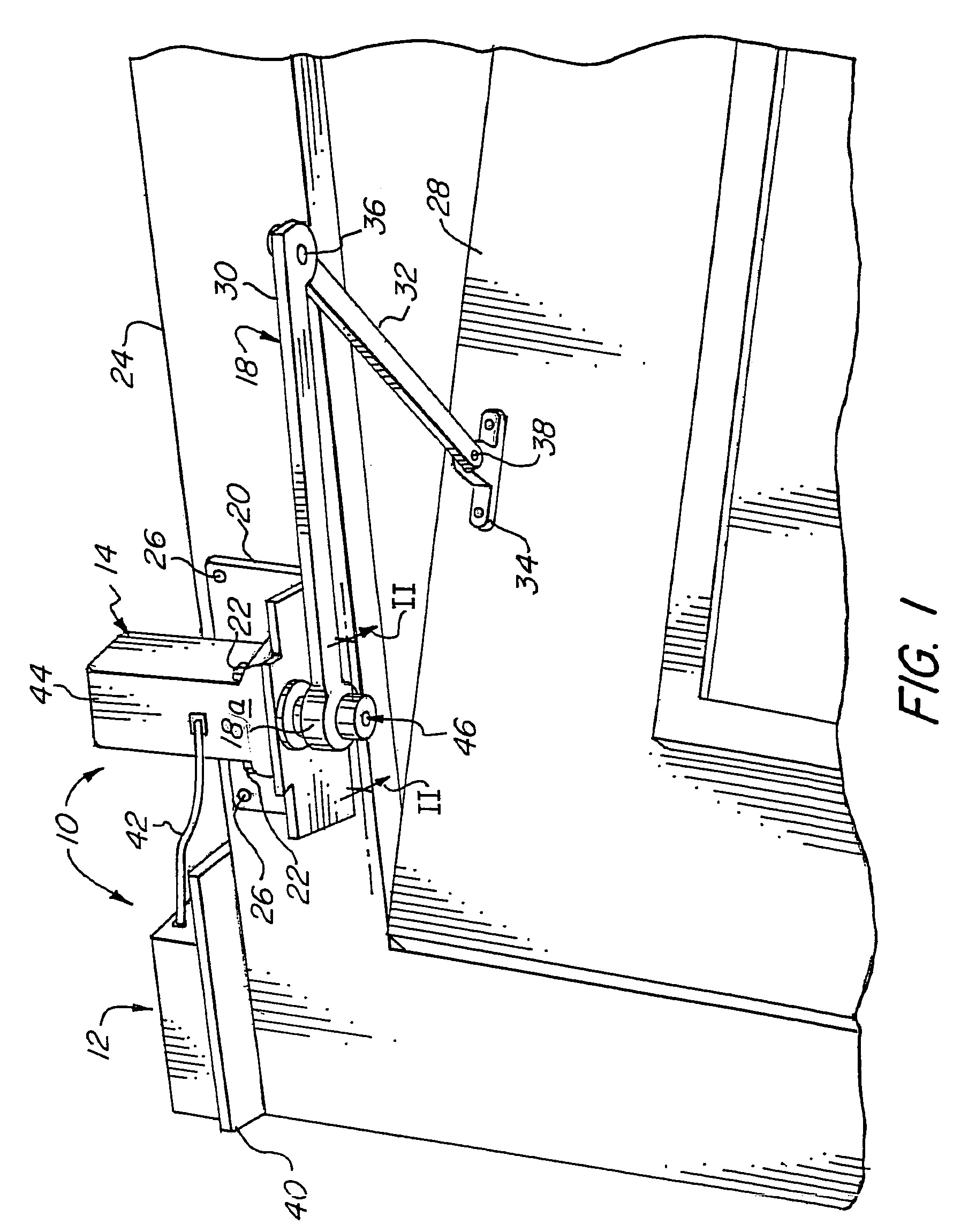
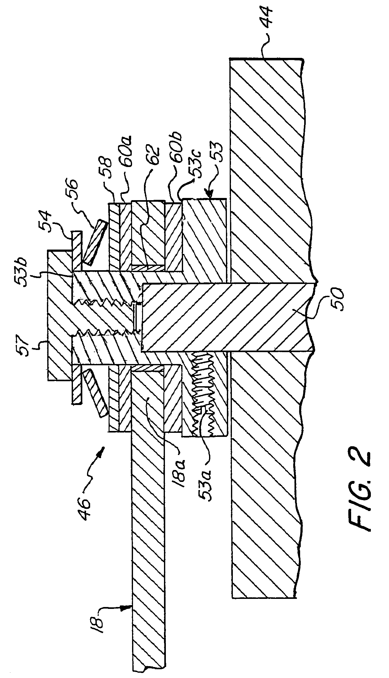
[0033]The present invention provides an automatic door opener for side hinged doors. The invention provides a motor connected via a clutch to swing an opener arm which in turn swings the door. The opener arm is mounted on an output shaft that directly drives the arm. According to one aspect of this invention, the clutch is mounted on the output shaft. According to another, separate aspect of this invention, the clutch and the hub of the opener arm are coaxially mounted on the drive shaft of the motor, i.e., the drive shaft of the motor serves as, or is at least coaxial with, the output shaft that drives the opener arm. This is in contrast to prior art designs in which slip clutches are mounted on intermediary gears in the drive train. Optionally, the clutch has a “self-contained” configuration when mounted on the opener arm so that it can easily be mounted on a drive shaft without affecting the slip characteristics. Also, the clutch may comprise an electromagnetic clutch.

[0034]Place...


PUM


Abstract

An automatic door opener (10) for opening or closing a door (28) includes a motor (14) driving a drive shaft (50) and an opener arm (18) connected to the door (28) and being responsive to rotation of the drive shaft (50) for moving the door (28) to an open or closed position. A clutch (46) operable to disengage the drive shaft (50) from the opener arm (18) is provided in the event of the door (28) engaging an obstacle, electric power being unavailable, or the door being fully open or fully closed. The door opener (10) may also include a brake (48) for selectively preventing movement of the door (28). Various embodiments of the invention are provided, including an electromagnet (80) and an electromagnetic brake (114).

Description

CROSS-REFERENCE TO RELATED APPLICATIONS[0001]This application is a continuation-in-part of application Ser. No. 09 / 952,225, now U.S. Pat. No. 6,634,140, filed Sep. 13, 2001, which claims the benefit of U.S. provisional patent application Ser. No. 60 / 232,296, filed Sep. 13, 2000, all of which is incorporated herein by reference.STATEMENT REGARDING FEDERALLY SPONSORED RESEARCH OR DEVELOPMENT[0002]Not Applicable.BACKGROUND OF THE INVENTION[0003]1. Field of the Invention[0004]The present invention relates generally to automatic side hinge door openers and, more particularly, relates to clutching and braking systems for use in conjunction with automatic door openers suitable for both original installation and easy retrofit onto standard side hinge doors.[0005]2. Related Art[0006]U.S. Pat. No. 5,878,530 to Eccleston et al, dated Mar. 9, 1999 and entitled “Remotely Controllable Automatic Door Operator Permitting Active And Passive Door Operation”, discloses a remotely controllable automati...

Claims


Application Information

Patent Timeline
Patent Type & Authority Patents(United States)
IPC IPC(8): E05F11/24E05F15/00E05F15/10E05F15/12
CPCE05F15/63E05F15/41E05Y2201/21E05Y2201/236E05Y2201/246E05Y2201/26E05Y2201/266E05Y2800/11E05Y2800/25E05F15/603E05Y2201/462E05Y2900/132E05Y2400/3013
Inventor SELLMAN, NILS D.
Owner POWER ACCESS
Learn More