Terminal crimping pliers

a crimping plier and pliers technology, applied in the field of pliers, can solve the problems of difficulty in fully grasping the plier by the user with small hands, difficulty in clamping, improperly applying force or inadequate force, etc., and achieves the effect of reducing the inconvenience of operation, facilitating the clamping, and being easy to be applied with for

Inactive Publication Date: 2007-12-18
PIN RUEI IND
View PDF6 Cites 3 Cited by
  • Summary
  • Abstract
  • Description
  • Claims
  • Application Information

AI Technical Summary

Benefits of technology

[0005]In view of the above problems, an object of the present invention is to provide a terminal crimping pliers, being easy to be held closed and easy to be applied with forces, thereby reducing the inconvenience of operation effectively. The structure of the stopping slot is improved, such that the horizontal moving distance of the locating bar is reduced, and accordingly the opening angle for the two handles will not be too large, and it is convenient for the user to operate.
[0006]In the terminal crimping pliers of the present invention, two handles are pivotally disposed with a pivot, and a locating bar is disposed at the top of the two handles respectively. The pivot and the two locating bars are received within each stopping slot respectively, and their moving distance is limited by each stopping slot, wherein the stopping slots for the two locating bars are leaned at an angle towards upward, such that the whole left / right moving distance in the horizontal direction is reduced, and therefore, the opening angle between the two handles is reduced, which is more suitable for operation.

Problems solved by technology

However, the structure of such a conventional terminal crimping pliers has a disadvantage in that, since the opening distance enables the collet 106 to return to the bottom, such that a terminal tab (not shown) can be conveniently inserted into the crimping hole 1071 above the collet 106, when the two handles 101, 102 are opened completely, and the angle is usually too large (as the stopping slot 1051 of the locating bar 105 is at horizontal position and the distance is too long), it is difficult for the user with small palms to grasp it completely.
In this way, to hold the two handles 101, 102 closed, a problem of it being difficult to apply forces thereon occurs.
That is, the user needs to grasp the handles with two hands to achieve the complete clamping (protruding) of the collet 106; otherwise, although it can be almost grasped, problems of improperly applying forces or applying inadequate forces will occur during clamping.

Method used


Image

  • Terminal crimping pliers
  • Terminal crimping pliers
  • Terminal crimping pliers

Examples


Embodiment Construction

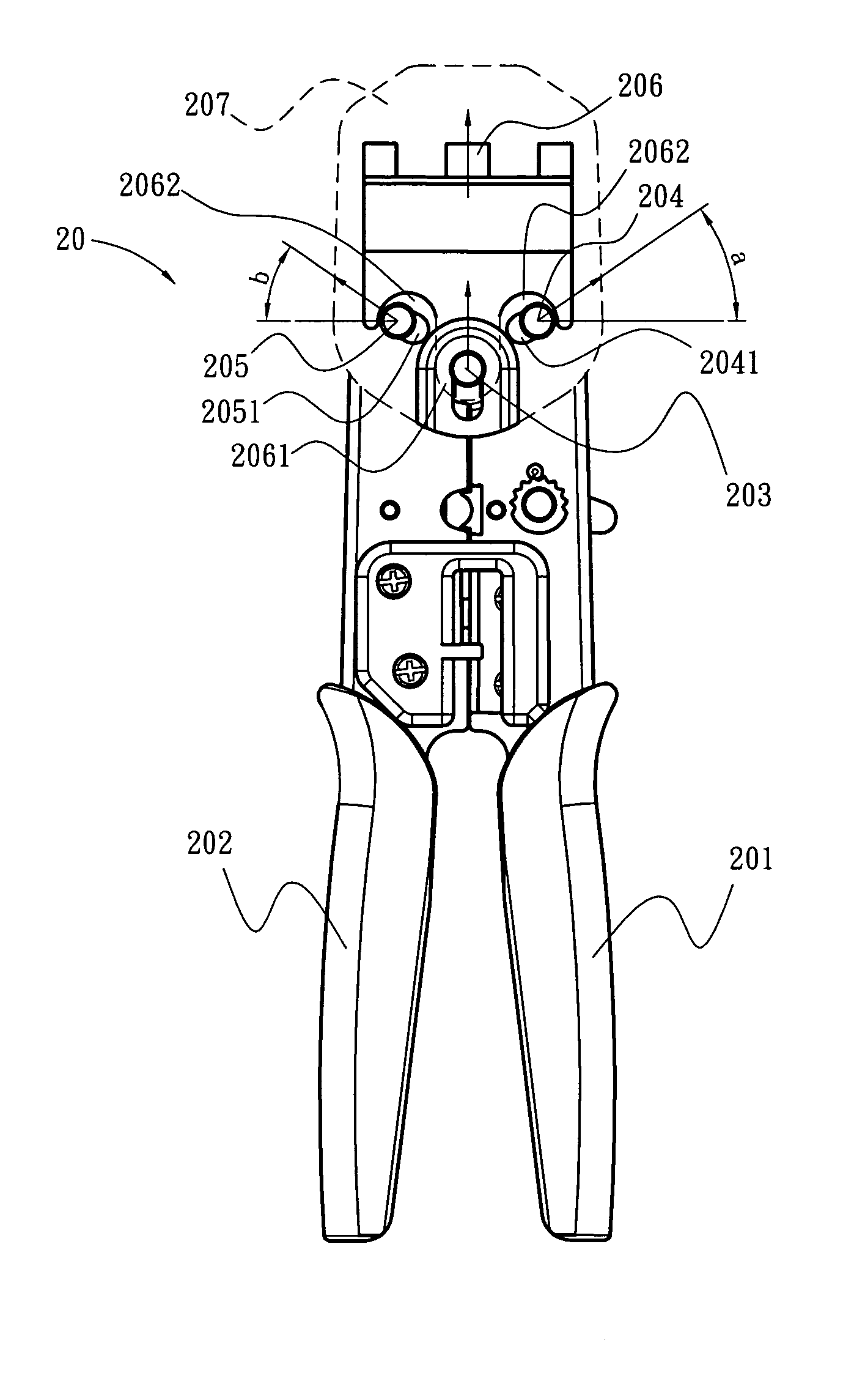
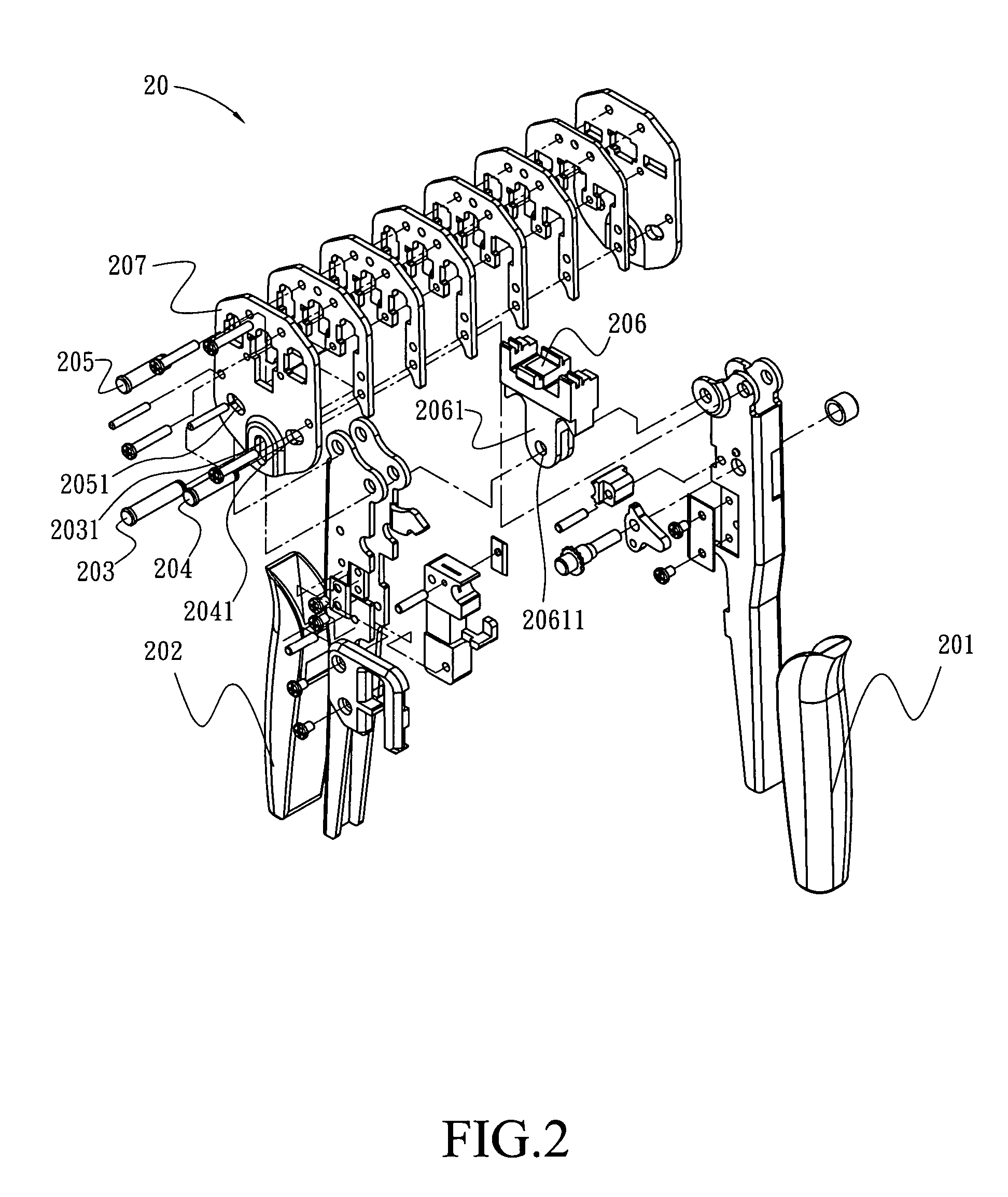
[0016]Referring to FIG. 2, it is a schematic view of the assembly of the present invention. As shown in the figure, as for the terminal crimping pliers 200 of the present invention, two opposing handles 201, 202 are pivotally disposed in a first stopping slot 2031 of an assembly board 207 through a pivot 203, and then the two opposing handles 201, 202 can be oppositely opened or closed. As shown, a first locating bar 204 and a second locating bar 205 are disposed adjacent to the top of the first stopping slot 2031, wherein the first locating bar 204 and the second locating bar 205 can pass through the handles 201, 202 via a second stopping slot 2041 and a third stopping slot 2051 of the assembly board 207. As shown, the assembly procedure for each element is that, the pivot 203, the first locating bar 204, and the second locating bar 205 pass through each stopping slot (the first stopping slot 2031, the second stopping slot 2041; and the third stopping slot 2051) of the assembly boa...


PUM

PropertyMeasurementUnit
distanceaaaaaaaaaa
forcesaaaaaaaaaa
electrical conductionaaaaaaaaaa

Abstract

A terminal crimping pliers is provided, which is designed with a simple structure, and is used to improve the disadvantages of the conventional terminal crimping pliers, such as being difficult to be grasped and difficult for forces applied thereon. The terminal crimping pliers can be extended with a small angle, through a vertical stopping slot combined with two stopping slots with oblique angles, and the terminal crimping pliers can be held closed with a small force.

Description

BACKGROUND OF THE INVENTION[0001]1. Field of Invention[0002]The present invention relates to a pliers exclusively used for manufacturing, assembling, maintaining or repairing line connectors, or current collectors, and more particularly, to a terminal crimping pliers for clamping a terminal tab with electrical connecting lines, which is much easier to be grasped and to be applied with forces thereon.[0003]2. Related Art[0004]The terminal crimping pliers connects a terminal and electrical connecting lines by way of clamping, thereby producing an electrical conduction. There are various kinds of conventional terminal crimping pliers, from early crimping pliers with a single function to current crimping pliers with multiple functions, such that a user can select suitable pliers optionally. The structural design of the terminal crimping pliers mainly utilizes the lever principle, such that the terminal crimping pliers can be clamped or released through the grasping or relaxing action of...

Claims


Application Information

Patent Timeline
Patent Type & Authority Patents(United States)
IPC IPC(8): H01R43/042
CPCH01R43/042Y10T29/5151Y10T29/53226
Inventor CHEN, CHING-JEN
Owner PIN RUEI IND
Why Eureka
Try Eureka