
Humidification system

a technology of humidification system and humidifier, which is applied in the direction of burners, multi-way valves, ratio control, etc., can solve the problems of affecting the treatment of cpap, the majority of patients experience significant side effects, and the difficulty of using cpap, so as to prevent mucosal drying, reduce nasal disease, and high humidity

Active Publication Date: 2007-12-11
FISHER & PAYKEL HEALTHCARE LTD
View PDF14 Cites 80 Cited by
  • Summary
  • Abstract
  • Description
  • Claims
  • Application Information

AI Technical Summary

Benefits of technology

The system provides precise control over gas conditions, reducing condensation and discomfort, and ensuring efficient water usage, making it suitable for various medical applications, including home care and surgical procedures, with improved patient outcomes and system simplicity.

Problems solved by technology

Treatment of OSA with nasal CPAP has proven to be both effective and safe, but CPAP is difficult to use and the majority of patients experience significant side effects, particularly in the early stages of treatment.
Upper airway symptoms adversely affect treatment with CPAP.
Mucosal drying is uncomfortable and may awaken patients during the night.
If untreated, upper airway symptoms adversely affect rates of use.
Also, at present there is no suitable means for home humidification of tracheotomy patients.
These patients have by-passed upper airways and are prone to infection and congestion.
The output is insufficient to prevent mucosal drying.
The formation of large quantities of water in the breathing tubing causes considerable inconvenience to the patient, may accelerate cooling of the gas, may eventually occlude the tubing, or may be expelled into the patient.
Also, the patient may experience discomfort, when breathing gases are delivered at temperatures widely divergent from that of the ambient temperature.
Excessive condensation also results in inefficient usage of the water in the humidifying chamber.
The temperature probe and its associated wiring included for this purpose make the attachment to the facemask or intubated patient bulky and therefore more uncomfortable for the patient Also for other medical procedures the probes and associated wiring also result in bulky attachments at the operation entry point causing obstructions to the surgeon or pressure sores around the point of entry.
With this system the humidity of the gases supplied to the patient is not accurate, particularly at high flows.

Method used


Image

  • Humidification system
  • Humidification system
  • Humidification system

Examples


Embodiment Construction

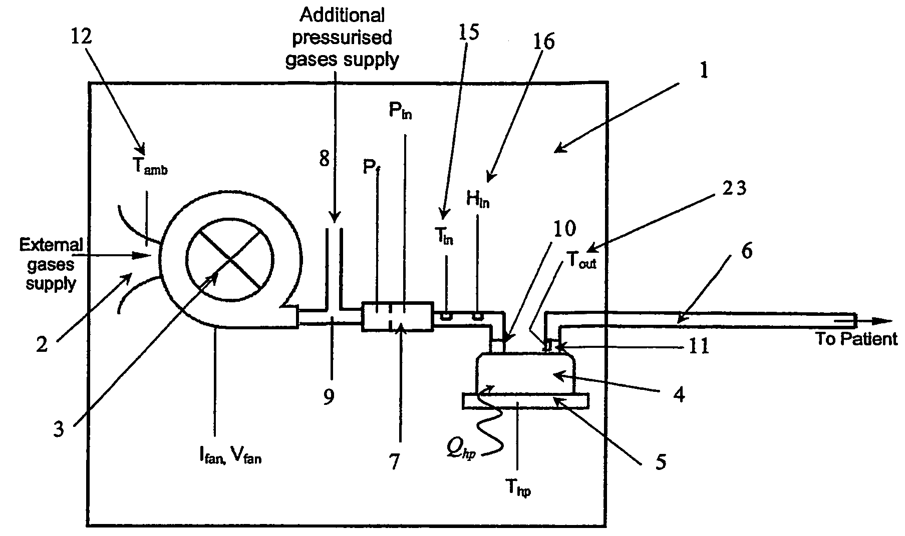
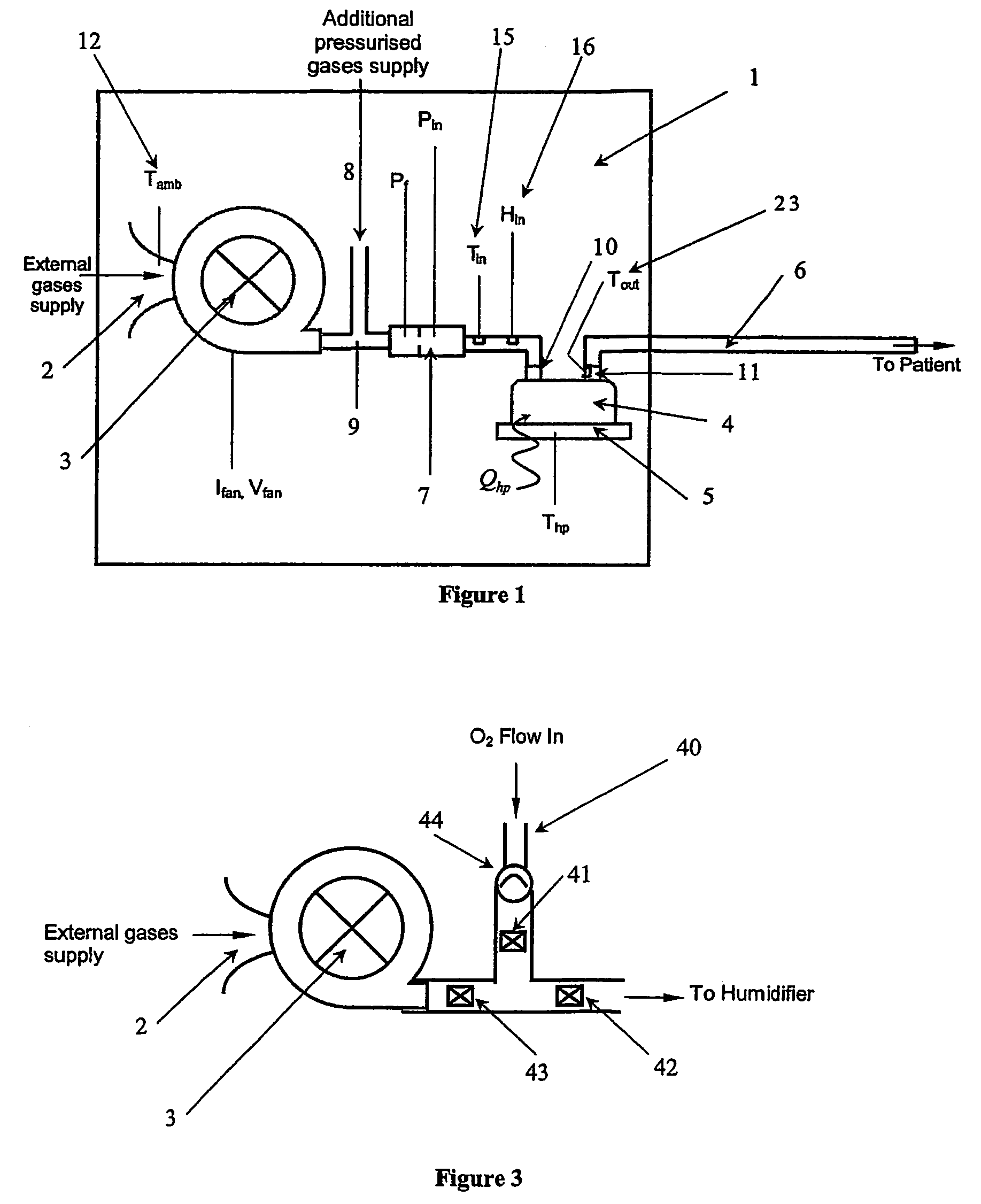
[0056]Whether used in a hospital environment or in a home care environment, the humidification system of the present invention will generally have associated with it a gases supply, such as ambient air, gases from cylinders, other compressed gas supply or gases from an insufflator, and a transport conduit from the humidification system to the patient, which is preferably heated to reduce condensation, or “rain out”.

[0057]A heating element is preferably provided within the conduit to help prevent condensation of the humidified gases within the conduit. Such condensation is due to the temperature of the walls of the conduit being close to the ambient temperature, (being the temperature of the surrounding atmosphere) which is usually lower than the temperature of the humidified gases within the conduit. The heating element effectively replaces the energy lost from the gases through conduction and convection during transit through the conduit. Thus the conduit heating element ensures th...


PUM

PropertyMeasurementUnit
temperatureaaaaaaaaaa

Abstract

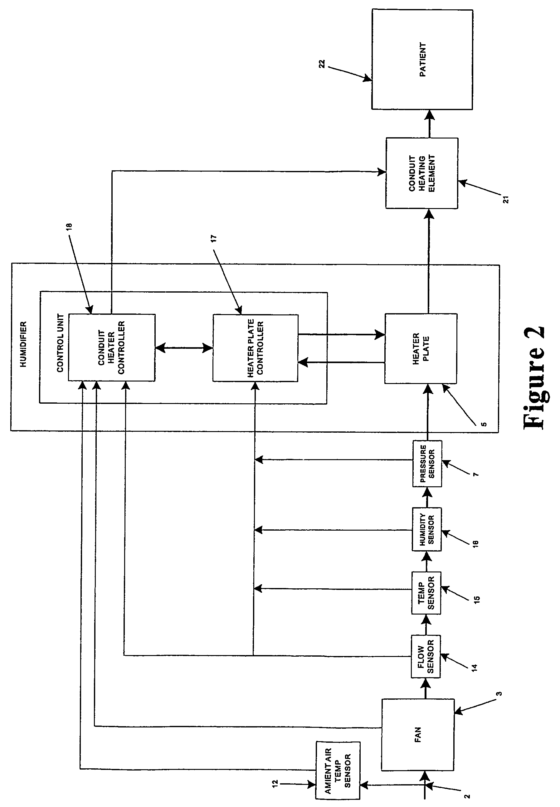
Breathing assistance apparatus including humidifier (4) and heated conduit (6) adapted to deliver humidified gases at desired and accurate level of humidity to patient. Humidifier includes controller (18) that delivers flow rate, temperature and humidity of gases and then determines required power input to deliver gases as required. Need for external sensors is dispensed with providing simple and less bulky apparatus.

Description

BACKGROUND OF THE INVENTION[0001]1. Field of the Invention[0002]This invention relates to a humidification system, particularly but not solely, for supplying optimal humidity temperature of gases to a patient to assist the patient's breathing for ventilation purposes, or for the supply of gases for other medical procedures, such as laparoscopic, endoscopic or ophthalmic procedures.[0003]2. Summary of the Prior Art[0004]A number of methods are known in the art for assisting a patient's breathing. Continuous Positive Airway pressure or CPAP involves the administration of air under pressure to a patient, usually by a nasal mask. It is used in the treatment of snoring and Obstructive Sleep Apnea (OSA), a condition characterised by repetitive collapse of the upper airway during inspiration. Positive pressure splints the upper airway open, preventing its collapse. Treatment of OSA with nasal CPAP has proven to be both effective and safe, but CPAP is difficult to use and the majority of pa...

Claims


Application Information

Patent Timeline
Patent Type & Authority Patents(United States)
IPC IPC(8): B01F3/04F24F6/00A61M16/00A61M16/10A61M16/16F24F6/02
CPCA61M16/1075A61M16/16A61M16/161A61M16/0069A61M16/109A61M16/1095A61M16/162A61M2016/0039A61M2202/0208A61M2205/3368A61M2205/17A61M16/107A61M16/168
Inventor HUDDART, BRETT JOHNMACKIE, SCOTT ROBERTWHITE, CRAIG KARL
Owner FISHER & PAYKEL HEALTHCARE LTD
Learn More