
Display methods and apparatus

a technology of mechanical light modulator and display method, applied in the field of video displays, can solve the problems that backlit displays using mechanical light modulator have not yet demonstrated sufficiently attractive combinations of brightness and low power, and achieve the effect of reducing rotation or other movemen

Inactive Publication Date: 2007-12-04
SNAPTRACK
View PDF363 Cites 79 Cited by
  • Summary
  • Abstract
  • Description
  • Claims
  • Application Information

AI Technical Summary

Benefits of technology

The invention relates to displays made from mechanical actuators with compliant electrodes. These actuators can be controlled by passive or active matrix arrays coupling controllable voltage sources to the voltage inputs of the actuators. The compliant electrodes can be positioned proximate to one another and can be drawn together by a voltage applied across them. The actuators can be coated with insulators to provide stiffness and the ability to interact with light. The actuators can be coupled to a modulator which controls the interaction with light. The modulator can be a shutter, a deformable mirror, a color filter, or a set of three color filters. The shutter can be in a mechanically bi-stable position between two stable positions, and the work needed to move it between the two positions is equal. The compliant member can be a curved compliant beam or a straight beam that forms an angle with the shutter in its stable positions. The invention provides a display apparatus with improved image quality and reduced latency.

Problems solved by technology

Backlit displays using mechanical light modulators have not yet demonstrated sufficiently attractive combinations of brightness and low power.

Method used


Image

  • Display methods and apparatus
  • Display methods and apparatus
  • Display methods and apparatus

Examples


Embodiment Construction

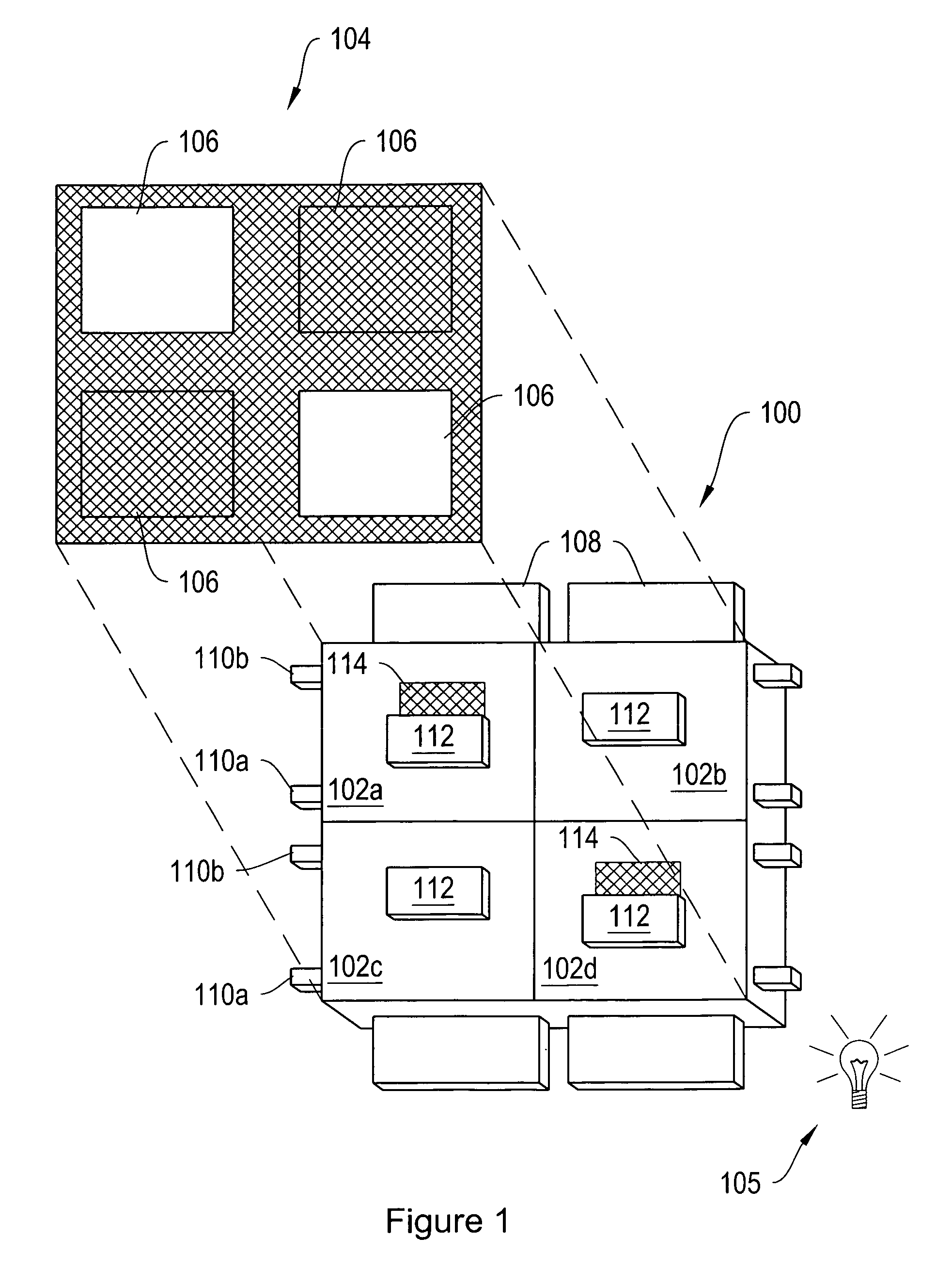
[0047]FIG. 1A is an isometric view of a display apparatus 100, according to an illustrative embodiment of the invention. The display apparatus 100 includes a plurality of light modulators, in particular, a plurality of shutter assemblies 102a-100d (generally “shutter assemblies 102”) arranged in rows and columns. In general, a shutter assembly 102 has two states, open and closed (although partial openings can be employed to impart grey scale). Shutter assemblies 102a and 100d are in the open state, allowing light to pass. Shutter assemblies 102b and 100c are in the closed state, obstructing the passage of light. By selectively setting the states of the shutter assemblies 102a-100d, the display apparatus 100 can be utilized to form an image 104 for a projection or backlit display, if illuminated by lamp 105. In another implementation the apparatus 100 may form an image by reflection of ambient light originating from the front of the apparatus. In the display apparatus 100, each shutt...


PUM


Abstract

The invention relates to light modulators for use in display apparatus. In particular, the invention relates to methods for supporting and support structures for light modulators to reduce unwanted motion.

Description

CROSS-REFERENCE TO RELATED APPLICATIONS [0001]This application is a continuation in part of U.S. patent application Ser. No. 11 / 218,690, filed Sep. 2, 2005. This application claims priority to, and the benefit of, U.S. Provisional Patent Application No. 60 / 676,053, entitled “MEMS Based Optical Display” and filed on Apr. 29, 2005; and U.S. Provisional Patent Application No. 60 / 655,827, entitled MEMS Based Optical Display Modules” and filed on Feb. 23, 2005. All three applications are incorporated herein by referenceFIELD OF THE INVENTION [0002]In general, the invention relates to the field of video displays, in particular, the invention relates to mechanically actuated display apparatus.BACKGROUND OF THE INVENTION [0003]Displays built from mechanical light modulators are an attractive alternative to displays based on liquid crystal technology. Mechanical light modulators are fast enough to display video content with good viewing angles and with a wide range of color and grey scale. M...

Claims


Application Information

Patent Timeline
Patent Type & Authority Patents(United States)
IPC IPC(8): G02B26/00G02B26/08
CPCG02B26/0841G02B26/02
Inventor HAGOOD, NESBITT W.STEYN, JASPER LODEWYK
Owner SNAPTRACK
Learn More