
Air quality monitoring systems and methods

a monitoring system and air quality technology, applied in the field of air quality monitoring systems and methods, can solve the problems of asthma incidence rate, aggravate the air quality problem, and inability to accept indoor air quality, and achieve the effect of increasing the scor

Inactive Publication Date: 2007-11-27
AIRCUITY
View PDF66 Cites 169 Cited by
  • Summary
  • Abstract
  • Description
  • Claims
  • Application Information

AI Technical Summary

Benefits of technology

Enables cost-effective, user-friendly, and real-time monitoring and analysis of indoor air quality, offering tailored solutions to improve air quality parameters and reduce the need for industrial hygiene professionals.

Problems solved by technology

However, inevitably the tradeoff sometimes results in unacceptable indoor air quality.
Moreover, the use of new building materials having many superior and desirable properties in both renovations of old buildings and new construction sometimes aggravates the air quality problems because the building materials outgas undesirable substances.
With respect to air quality in the home or in schools, incidence rate of asthma, which is often triggered by poor indoor air quality, is growing exponentially.
Thus, indoor air quality is an issue of great importance in residential, commercial and industrial environments.
Unfortunately, it is currently very expensive to obtain a customized indoor air quality assessment of a building plus a customized set of recommendations to solve any potential air quality problems uncovered.
To accomplish this today requires the use of costly, hard to apply instruments and the expertise of relatively expensive industrial hygiene professionals.
However, without indoor air quality expertise to evaluate a specific building's situation, this generalized information is of only limited value.
Similarly, instruments can be rented to take specific measurements, but this can be very time consuming and expensive.
Moreover, useless data can be generated without properly taking into account building specific data and information to properly set up the instruments and determine where and when to run a test.
Furthermore, without monitoring, analyzing and adapting the data taking process in real time, based on the real time data from the instruments, important events and trends can easily be missed.
Additionally, problems in the instruments or their locations can render a whole series of measurements useless.
Beyond the use of an industrial hygienist employing sophisticated air measurement instruments, there have been only limited options to help the building owner or occupant obtain information about the air quality of their environment.
Although convenient for a customer, there is no analysis of the data, nor is there any way for the system to adapt its operation or to be customized automatically based on the specific building being measured or the data that is gathered.
However, it does not describe any methods for customizing the data taking process to a given building or analyzing the data that is taken.
Some available devices measure and data log some environmental air parameters and then send emails to a customer based on predetermined levels being exceeded, but do not take into account anything more sophisticated in their analysis of the data.
Nor do these devices employ any method to reprogram or modify the testing program remotely.
However, this device is not designed for indoor use, requires intervention of a trained operator to decide when to take the sample and involves expensive technology with limited range due to the use of radio wave communication for transmission to the device.
None of the prior art disclosed provides the user with customized information and recommendations about the air quality within or immediately around a specific building.

Method used


Image

  • Air quality monitoring systems and methods
  • Air quality monitoring systems and methods
  • Air quality monitoring systems and methods

Examples


Embodiment Construction

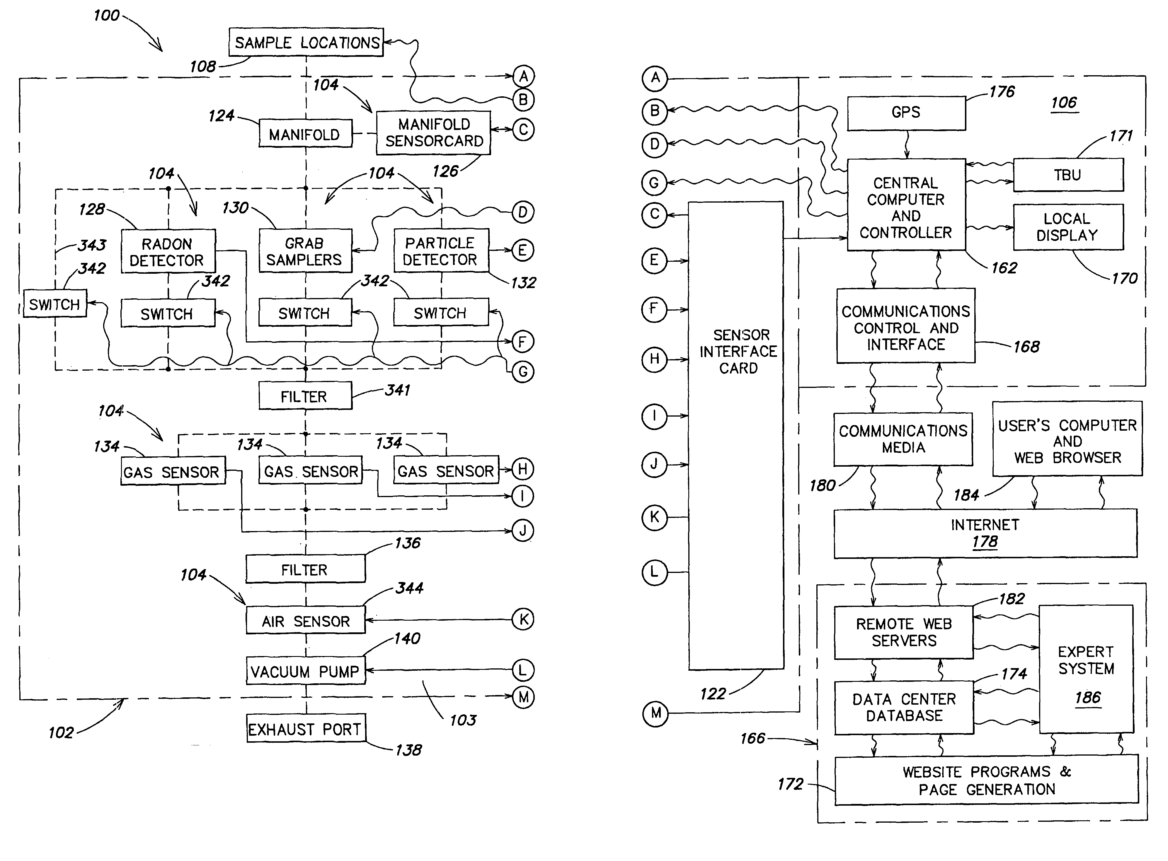
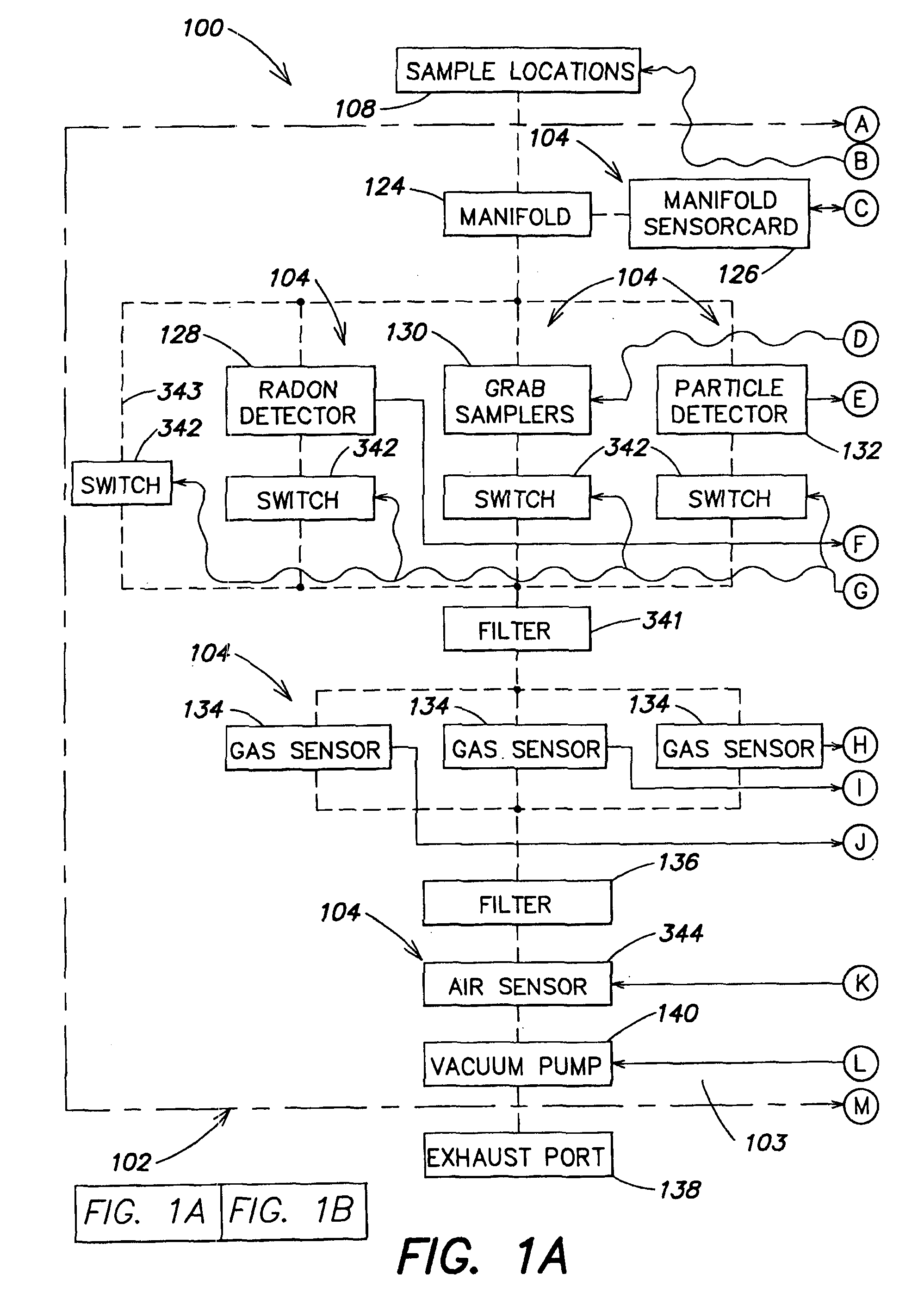
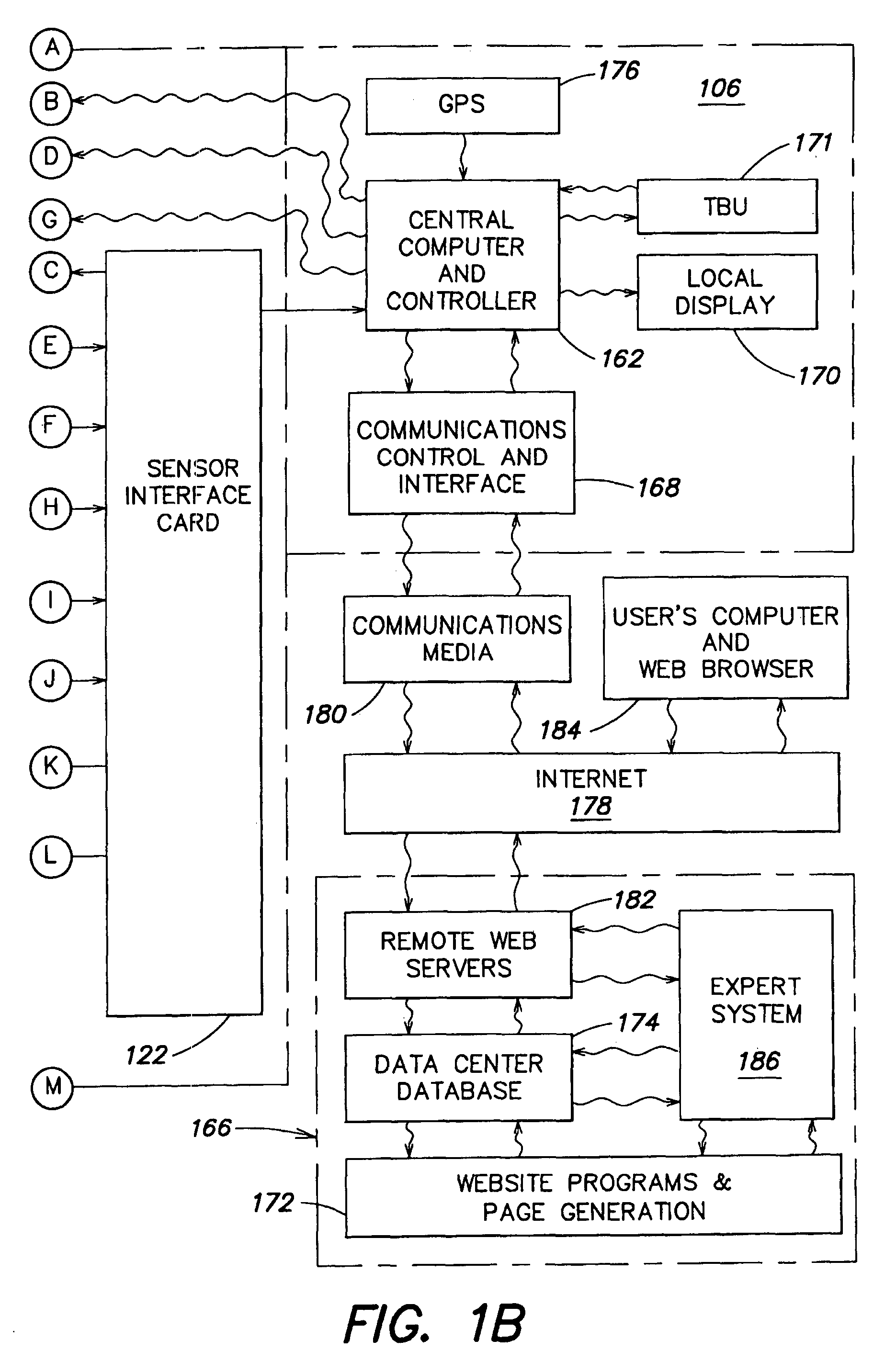
[0041]Referring to FIGS. 1A and 1B, a schematic block diagram of one embodiment of an air monitoring system 100 according to the present invention is shown. The air monitoring system may be a portable or an installed system, or a system having a combination of portable and installed components. The air monitoring system 100 includes an air monitoring unit 102. In a portable system, the air monitoring unit 102 may be hand held or reasonably portable. The air monitoring unit includes a sensor unit 103 having at least one sensor 104 and a control unit 106. In a portable system the air to be sampled, or sample locations 108, may be taken from the area immediately surrounding the air monitoring unit or through a tube (not shown) from one or more remote sample locations.

[0042]An installed system may have many different configurations. The installed system may include an air monitoring unit 102 installed in a building to monitor one or more spaces within the building. Referring to FIG. 2, ...


PUM

PropertyMeasurementUnit
sizeaaaaaaaaaa
sizeaaaaaaaaaa
timeaaaaaaaaaa

Abstract

An air monitoring system is disclosed having an air monitoring unit with at least one sensor for measuring data of an air quality parameter and a computer for storing the air quality parameter data received from the sensor. The air monitoring unit may use an installed or a portable system, or a combination of both, for measuring the air quality parameters of interest. A remote data center may be provided, and the data may be uploaded to the data center from the unit by a communications media such as the Internet. Information or instructions may also be downloaded from the data center to the unit via the communications media for controlling or modifying the function of the unit. An expert system may be provided with the air monitoring system for controlling the unit. The information or instructions downloaded to the unit may be generated by the expert system.

Description

FIELD OF THE INVENTION[0001]This invention relates to air quality monitoring systems and methods. More particularly, this invention relates to an air monitoring system that is customized for a specific structure, such as a building or a home, and / or the occupants. Still more particularly, the air monitoring system measures certain air quality parameters and may provide an analysis of the data collected and may make recommendations for improving the air quality parameters.BACKGROUND OF THE INVENTION[0002]Over time people have become more energy-conscious. Because of this, the construction industry started building structures that are far “tighter” than their predecessors, with respect to air leakage. Buildings are now carefully designed to provide occupants with a precisely metered exchange between indoor and outdoor air. The exchange between indoor and outdoor air is selected to provide a healthy quality of indoor air, with a minimum of energy usage for heating or cooling the outdoo...

Claims


Application Information

Patent Timeline
Patent Type & Authority Patents(United States)
IPC IPC(8): G08B17/117G01N27/416G01N27/12F24F11/02G01N1/22G01N1/24G01N1/26G01N15/06G01N27/00G01N33/00
CPCG01N1/26G01N33/0075G01N33/0034G01N1/2273G01N1/24Y10S706/93G01N2001/021E05Y2800/22
Inventor SHARP, GORDON P.SCHWARTZ, JEFFREY P.BUZZEO, DAVID J.DESROCHERS, ERIC M.FARRINGTON, DAVID L.
Owner AIRCUITY
Learn More