
Low cost RFID system

a low-cost, rfid technology, applied in the direction of burglar alarm mechanical actuation, electromagnetic radiation sensing, instruments, etc., can solve the problems of inability to separate or individually ascertain signals, difficult to send constant signals combined with backscattered response signals, etc., and achieve the effect of low cos

Inactive Publication Date: 2007-11-13
SUPERVISION LLC
View PDF17 Cites 12 Cited by
  • Summary
  • Abstract
  • Description
  • Claims
  • Application Information

AI Technical Summary

Benefits of technology

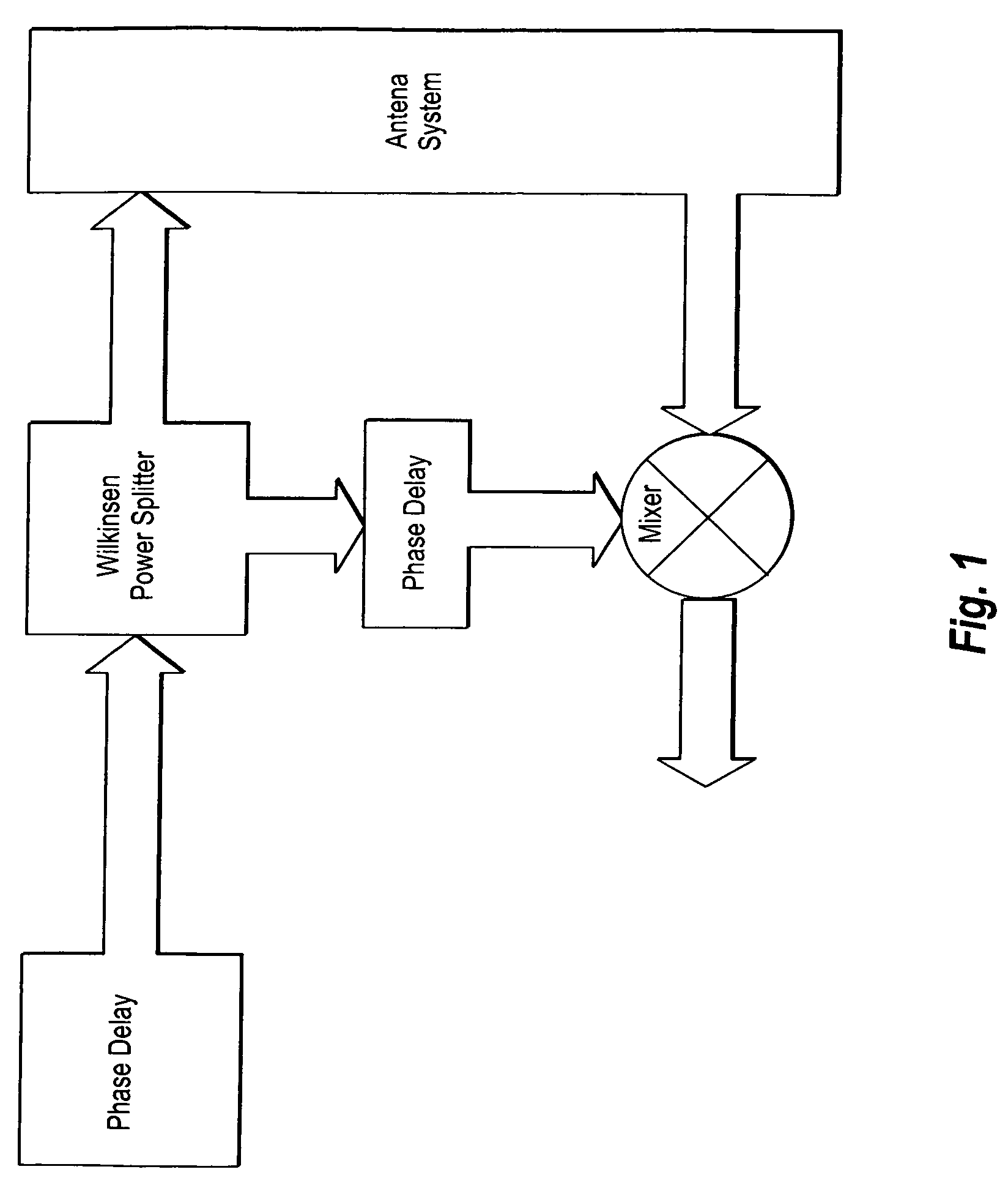
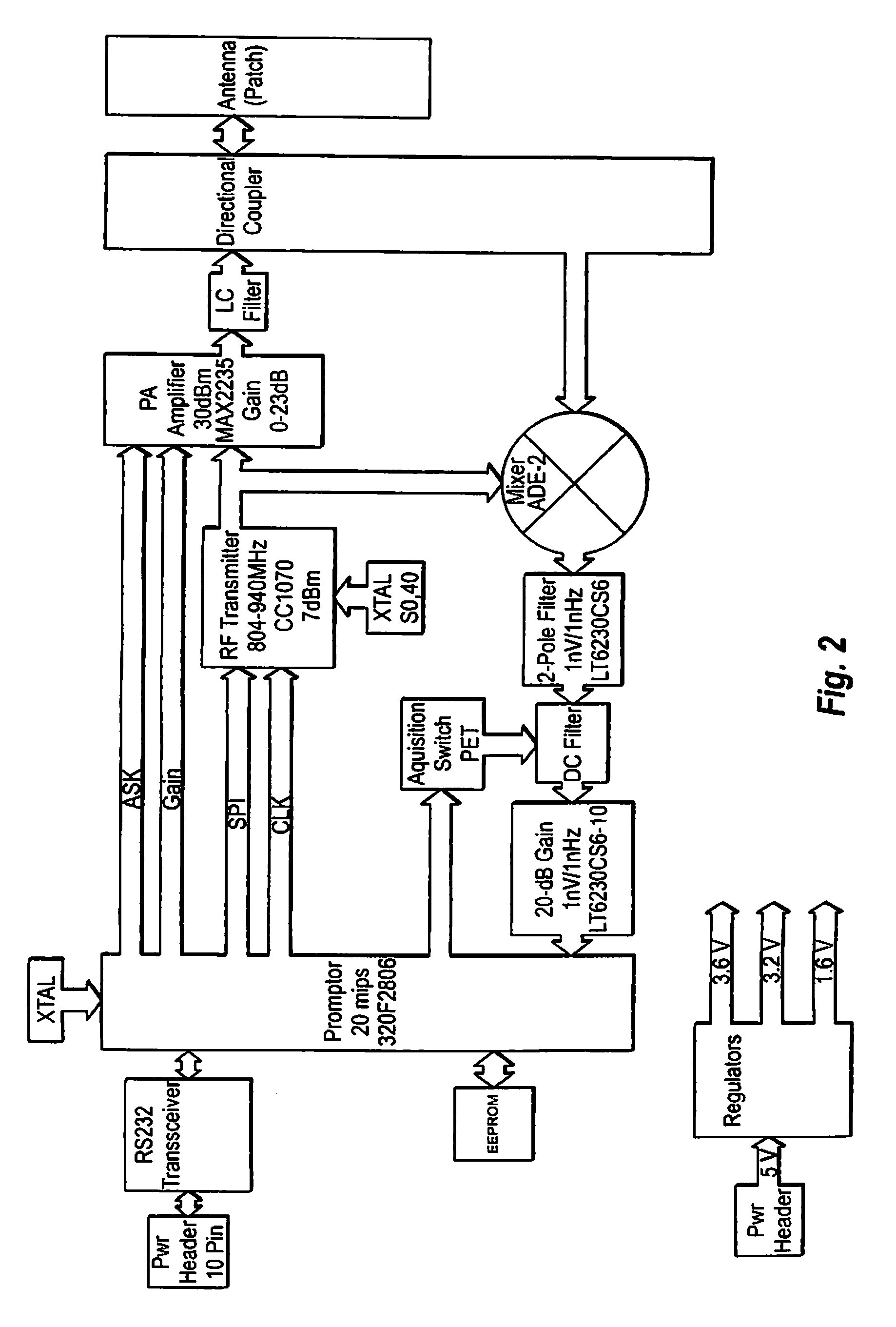
[0014]The present invention is a low cost radio frequency identification system that allows interactions between a reader / writer and an individual tag at close range in environments where multiple tags exist. The system includes a reader / writer that can both read and write EPC class 1 and Gen2 tags and includes the features necessary to identify the tag, verify proper operation, and optionally write specific data to the tag under the direction of a host controller. The system allows for these steps to be performed even when a plurality of other tags are in close proximity to the target tag.

Problems solved by technology

In some circumstances, this constant sending of a signal combined with the backscattered response signals can be problematic particularly in applications where the reader is in close association with a plurality of tags or when the reader and the tags are in close contact with one another.
This results in signals which are difficult to separate or individually ascertain.
Various attempts to separate these signals and these tags have proved to be either too expensive or technically unsuitable for use in such a system.
These weaknesses in the present systems have made the programming of RFID labels from a single location or device very difficult.
Where such systems have been implemented, the equipment utilized to achieve these results has been too expensive to allow for widespread use of this technology or the use of this technology in conjunction with the many items in common commerce.
However, this methodology typically requires a large area to implement and further requires site specific research to evaluate the amount of isolation that can be achieved in a specific production environment.
However, the cost of these parts makes them so expensive so as to reduce their applicability and use in various aspects of industry or commerce.

Method used


Image

  • Low cost RFID system
  • Low cost RFID system
  • Low cost RFID system

Examples


Embodiment Construction

[0033]While the invention is susceptible of various modifications and alternative constructions, certain illustrated embodiments thereof have been shown in the drawings and will be described below in detail. It should be understood, however, that there is no intention to limit the invention to the specific form disclosed, but, on the contrary, the invention is to cover all modifications, alternative constructions, and equivalents falling within the spirit and scope of the invention as defined in the claims.

[0034]The preferred embodiment of the present invention is a system for RFID communications. A key component of this invention is a RFID reader / writer device that is preferably configured to operate in the ISM band of 902 to 928 megahertz in the U.S. utilizing a frequency hopper spread spectrum or FHSS technique to meet appropriate FCC requirements. In other countries, the particular bandwidth in which the device operates can be varied so as to comply with the specific necessities...


PUM


Abstract

A low cost close range RFID Reader / Writer which is operatively connected to a control device which contains a transmitter and is configured to function as a homodyne receiver. The device can be constructed from low cost parts and can function in close ranges to other tags. The present invention provides increased RFID identification and isolation properties and is suitable for inclusion and operative use with a variety of applications.

Description

BACKGROUND OF THE INVENTION[0001]1. Field of the Invention[0002]The present invention generally relates to identification systems and more particularly to wireless identification systems that utilize electronically sensitive tags to store and provide identification information.[0003]2. Background Information[0004]Radio Frequency Identification Systems (RFIDs) are used in a variety of industries to identify, track, and provide various other types of information related to the items upon which the tag is placed. A typical RFID system is usually made up of at least one transmitting and receiving device commonly called a reader and at least one passive or active target device, typically called a tag. The basic principal of this system involves the transmission of radio frequency energy from the reader to the tag. The tag receives the signal, modifies that energy and reflects this modified signal back to the reader, where the reflected and modified return signal is received, read and dec...

Claims


Application Information

Patent Timeline
Patent Type & Authority Patents(United States)
IPC IPC(8): G08B13/14
CPCG06K7/0008
Inventor JESSUP, STEVENHICKSTED, RICHARD L.SPAHR, MICHAEL A.
Owner SUPERVISION LLC
Learn More