
Bone fixation apparatus

a bone fixation and bone technology, applied in the field of medical devices, can solve the problems of difficult mateing of threads, considerable pain for patients with such injuries,

Inactive Publication Date: 2007-11-13
NAS MEDICAL TECH
View PDF37 Cites 178 Cited by
  • Summary
  • Abstract
  • Description
  • Claims
  • Application Information

AI Technical Summary

Problems solved by technology

Patients with such injuries can experience considerable pain.
However, because the fastener is threaded into the support structure during the course of surgery, it can be difficult to mate the threads accurately in a tight surgical field and there is the possibility of cross threading the screw.

Method used


Image

  • Bone fixation apparatus
  • Bone fixation apparatus
  • Bone fixation apparatus

Examples


Embodiment Construction

[0028]Embodiments of the invention will now be described with reference to the accompanying Figures, wherein like numerals refer to like elements throughout. The terminology used in the description presented herein is not intended to be interpreted in any limited or restrictive manner, simply because it is being utilized in conjunction with a detailed description of certain specific embodiments of the invention. Furthermore, embodiments of the invention may include several novel features, no single one of which is solely responsible for its desirable attributes or which is essential to practicing the inventions herein described.

[0029]The foregoing description details certain embodiments of the invention. It will be appreciated, however, that no matter how detailed the foregoing appears in text, the invention can be practiced in many ways. As is also stated above, it should be noted that the use of particular terminology when describing certain features or aspects of the invention sh...


PUM


Abstract

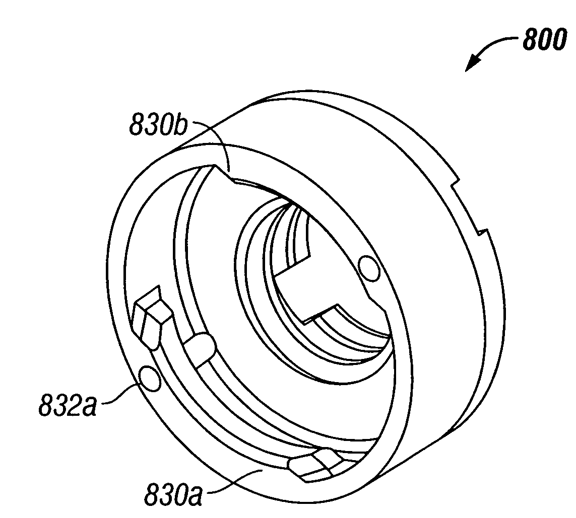
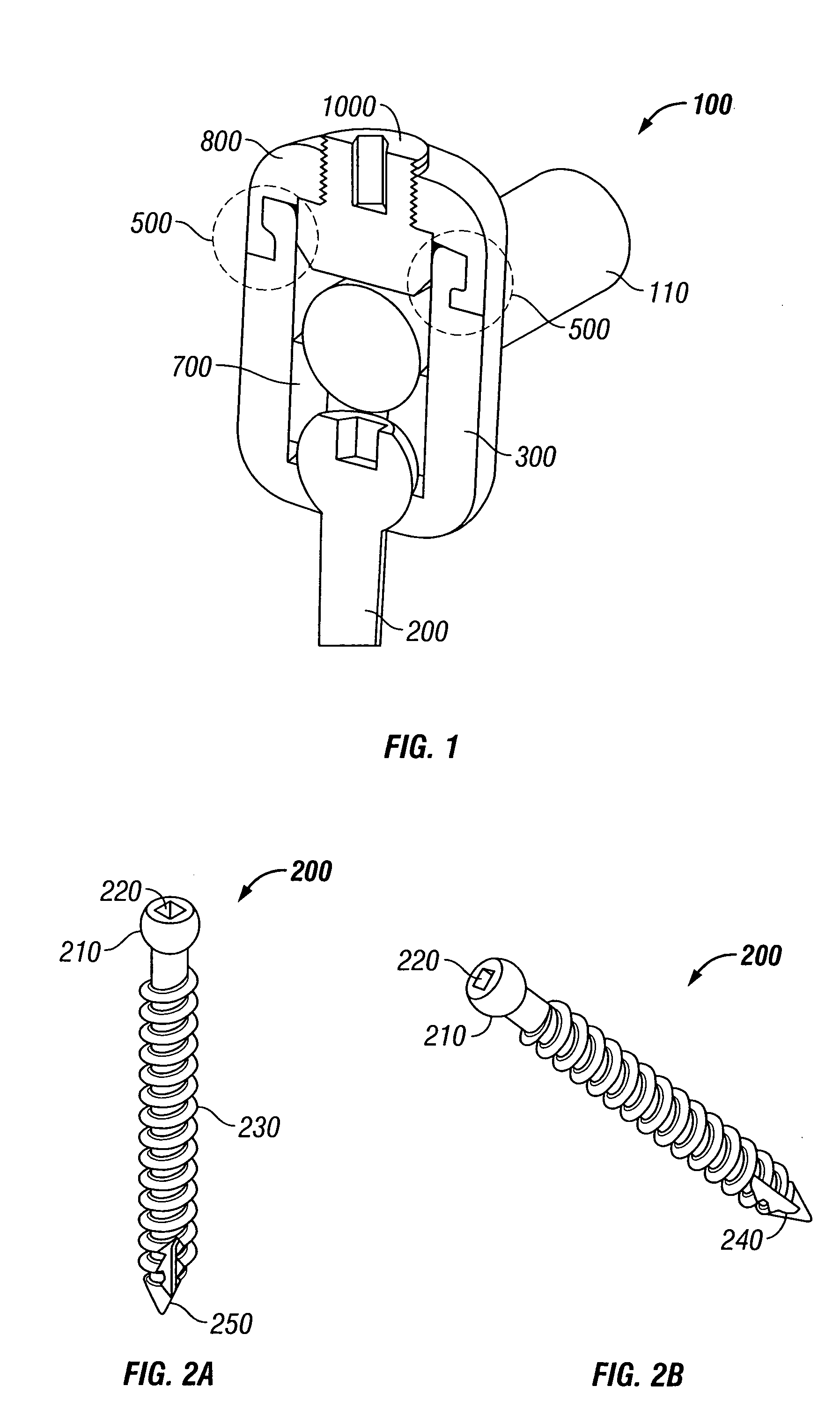
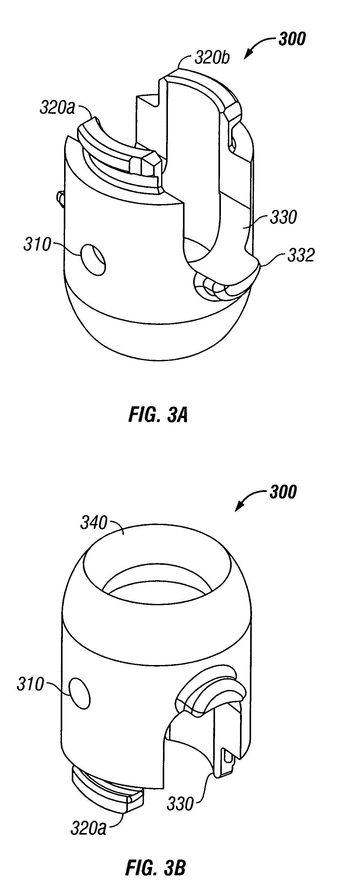
A bone fixation apparatus adapted for use in spinal stabilization. The apparatus includes a threaded bone screw having a spherical head that is received in a receiver cup. The receiver cup also includes a slot or groove through which a support rod passes. A saddle is positioned in the receiver cup below the support rod and above the head of the threaded bone screw. Alignment flanges are positioned partially around an opening on the receiver cup opposite the bone screw. A cap having internal grooves corresponding to the alignment flanges mates with the receiver cup. The cap may be positioned onto the receiver cup in a first orientation and secured to the receiver cup by rotating approximately one quarter turn. A compression member is screwed into internal threads on an opening of the cup to provide pressure on the support rod, thereby fixing the rod to the receiver cup.

Description

RELATED APPLICATIONS[0001]This application claims the benefit of U.S. Provisional Application No. 60 / 371,602, filed Apr. 9, 2002, entitled “SPINAL SCREW APPARATUS”, the entirety of which is hereby incorporated herein by reference.BACKGROUND OF THE INVENTION[0002]1. Field of the Invention[0003]The invention relates to the field of medical devices. More particularly, the invention relates to a bone fixation apparatus.[0004]2. Description of the Related Art[0005]Injuries to the spine can occur from fractures of vertebra, bulging or slipped disks, infections, tumors, and other sources. Patients with such injuries can experience considerable pain. Some types of spinal injuries may be corrected through spinal surgery. In one type of spinal surgery, two or more adjacent vertebrae are fused together.[0006]In order to fuse two vertebrae together, an incision is made over the location to be fused. Bone and tissue are removed from the joint to allow the vertebrae to fuse together into one unit...

Claims


Application Information

Patent Timeline
Patent Type & Authority Patents(United States)
IPC IPC(8): A61B17/56A61F2/30A61B17/70
CPCA61B17/7037A61B17/7032
Inventor ALLEYNE, NEVILLENONAKA, MAKOTO
Owner NAS MEDICAL TECH
Learn More