Fine-adjustment mechanism for scanning probe microscopy
a technology of fine adjustment and scanning probe, which is applied in the direction of mechanical roughness/irregularity measurement, instrumentation, etc., can solve the problems of deteriorating measurement accuracy, reduce wiring, increase the rigidity of the unit, and reduce the number of resistors
- Summary
- Abstract
- Description
- Claims
- Application Information
AI Technical Summary
Benefits of technology
Problems solved by technology
Method used
Image
Examples
first embodiment
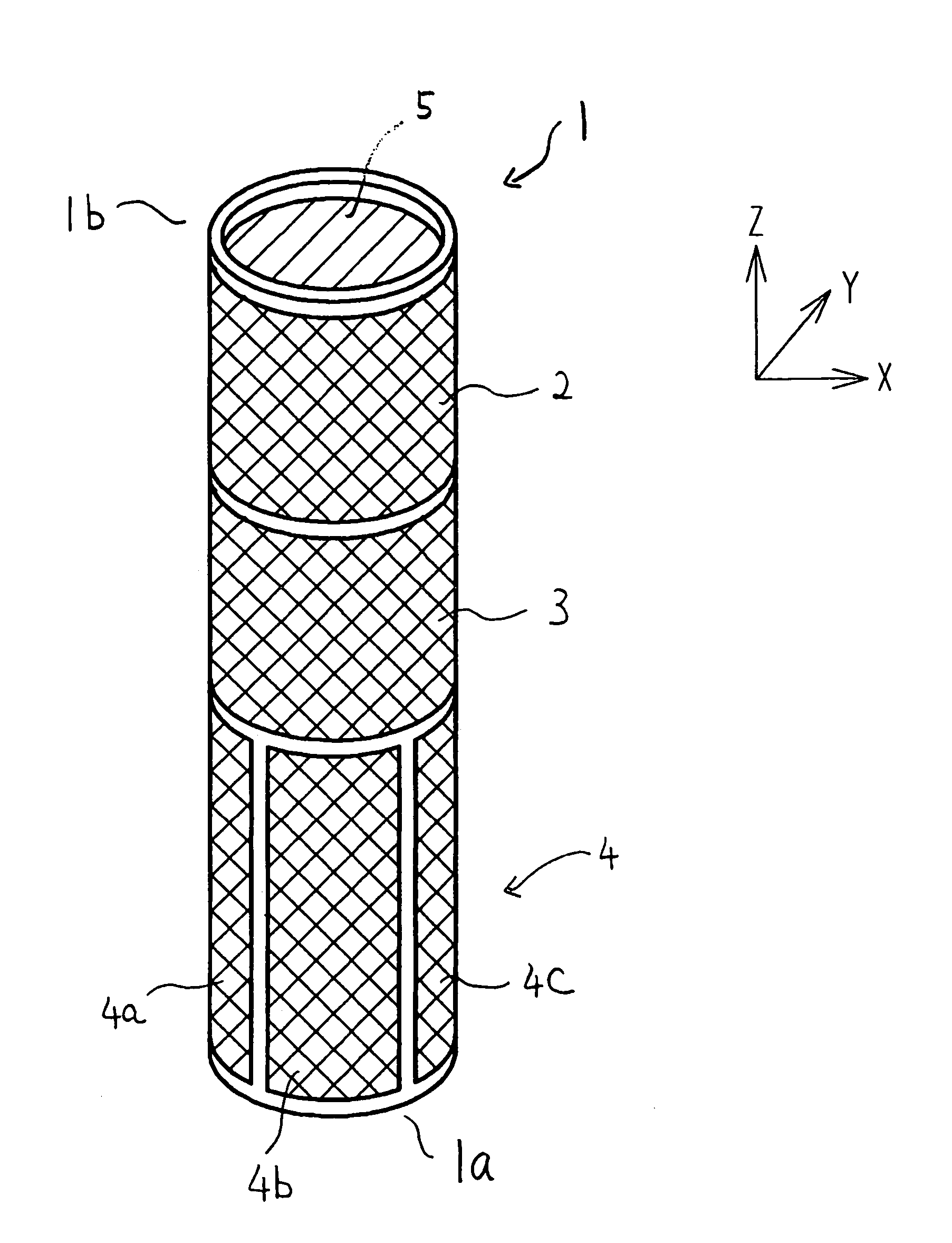
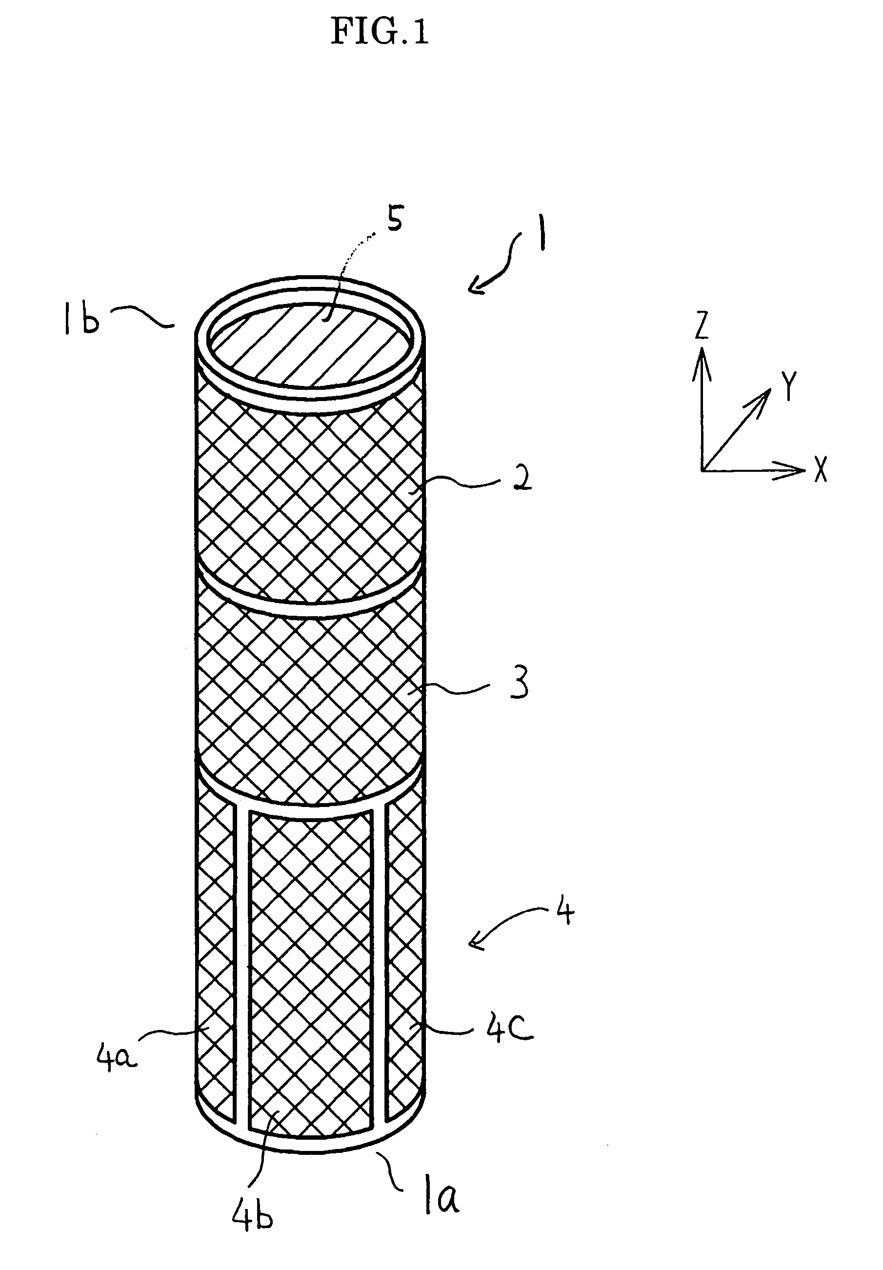
[0064]A first embodiment of a fine-adjustment mechanism for a scanning probe microscopy of the invention is shown in FIG. 1 to FIG. 4. FIG. 1 is an outline view of a fine-adjustment mechanism formed of a cylindrical piezoelectric device according to the first embodiment of the invention.
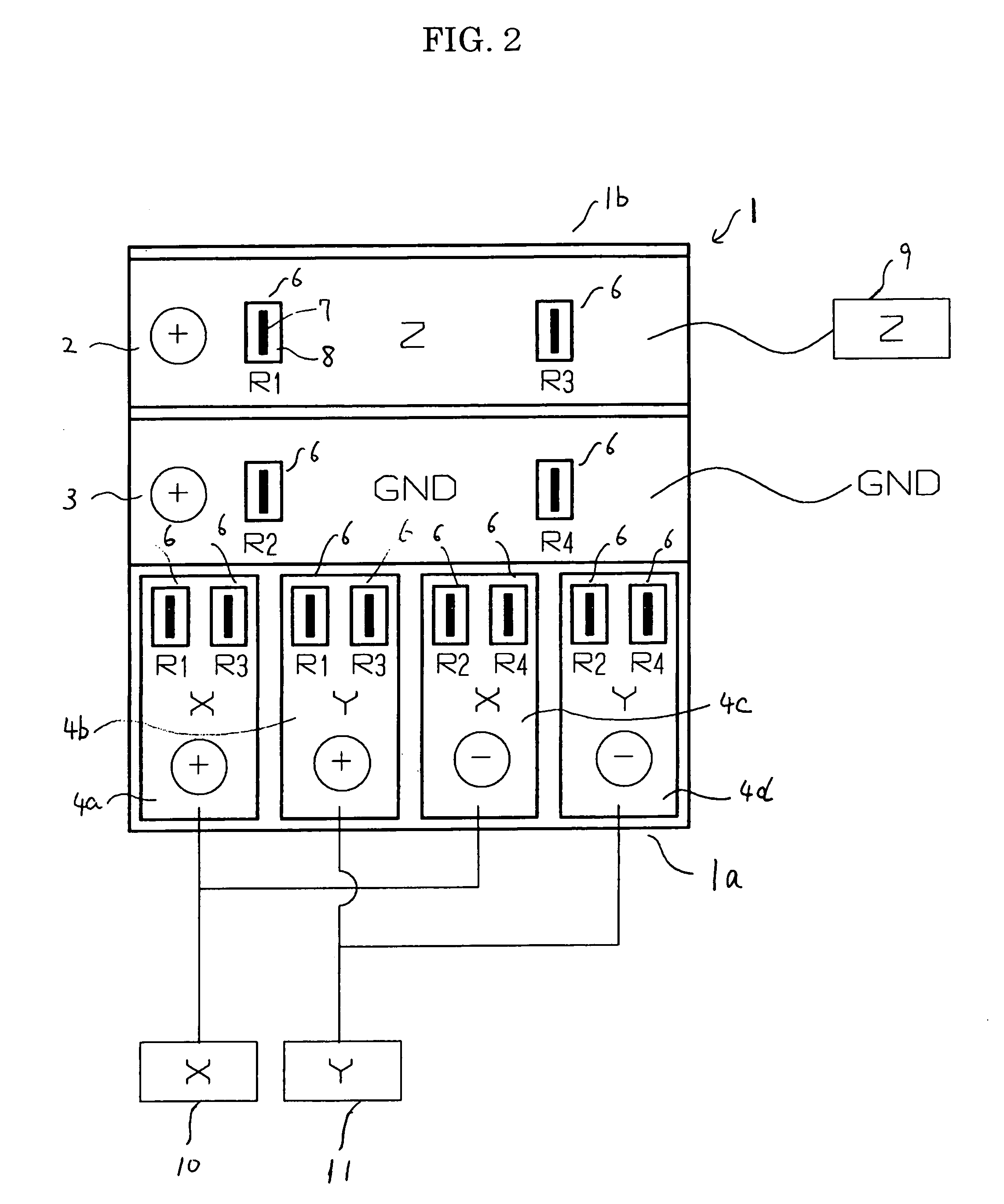
[0065]In the first embodiment, a cylindrical piezoelectric device 1 is formed by forming the piezoelectric device into a hollow cylindrical shape as shown in FIG. 1. A common electrode 5 is provided within the cylindrical piezoelectric device 1. The entire outer periphery of the cylindrical piezoelectric device 1 is divided into three levels of a first level (upper level), a second level (middle level), and a third level (lower level) from the distal end 1b to the proximal end 1a. A Z-electrode 2 used as an active electrode for generating strain toward the center axis of the cylinder and a dummy electrode 3 used as a dummy electrode are provided on the two levels of the first level and the second lev...
second embodiment
[0097]Subsequently, referring to FIG. 5, FIG. 6 and FIG. 7, a second embodiment of the fine-adjustment mechanism for the scanning probe microscopy will be described. The common components to the respective components described in the first embodiment are represented by the same reference numerals and the common contents relating to the structure or operation among the respective components will not be described in detail.
[0098]The fine-adjustment mechanism according to the second embodiment also employs the cylindrical piezoelectric device 1 having the same shape as in the first embodiment shown in FIG. 1. FIG. 5 is an expansion plan of the outer peripheral surface of the cylindrical piezoelectric device, showing adhesion of the strain gauges, polarities of poling (plus and minus signs), and wiring for high voltage to be applied to the respective electrodes
[0099]In the second embodiment, two strain gauges Rz1, Rz3 are adhered on the band-shaped Z-electrode 2 for fine-adjustment in t...
PUM
| Property | Measurement | Unit |
|---|---|---|
| resistance | aaaaa | aaaaa |
| resistance | aaaaa | aaaaa |
| scanning probe microscopy | aaaaa | aaaaa |
Abstract
Description
Claims
Application Information
 - R&D
- Intellectual Property
- Life Sciences
- Materials
- Tech Scout
- Unparalleled Data Quality
- Higher Quality Content
- 60% Fewer Hallucinations
Browse by: Latest US Patents, China's latest patents, Technical Efficacy Thesaurus, Application Domain, Technology Topic, Popular Technical Reports.
© 2025 PatSnap. All rights reserved.Legal|Privacy policy|Modern Slavery Act Transparency Statement|Sitemap|About US| Contact US: help@patsnap.com


