
Swing hinge device of portable terminal

a portable terminal and hinge device technology, applied in the direction of hinges, wing accessories, manufacturing tools, etc., can solve the problems of inability to provide practical means to implement the opening and closing operation of conventional portable terminals, damage to the fpcb positioned between the pair of housings, etc., and achieve the effect of convenient terminal opening and closing operation

Inactive Publication Date: 2007-10-30
SAMSUNG ELECTRONICS CO LTD
View PDF19 Cites 19 Cited by
  • Summary
  • Abstract
  • Description
  • Claims
  • Application Information

AI Technical Summary

Benefits of technology

The present invention provides a swing hinge device for a portable terminal that allows for easy opening and closing of the terminal. The device includes a hinge housing, a hinge shaft, and a hinge cam. The hinge cam is positioned in the hinge housing and is elastically forced against the hinge shaft by a hinge spring. A hinge stopper is positioned between the hinge housing and the hinge shaft to limit the range of rotation of the hinge shaft and prevent damage to the terminal. The hinge shaft has crests that face the troughs on the hinge cam, allowing for smooth rotation of the terminal. The device also includes a hinge module slanted at a predetermined angle relative to the terminal housings for improved opening and closing operation.

Problems solved by technology

However, practical means to implement the opening and closing operation of conventional portable terminals has not been provided.
In particular, swing-type terminals that implement opening and closing operation by rotating a pair of housings while they face each other have a problem in that, in order to open the terminals for speech, the user must manually rotate one housing to a speech position.
In addition, when one housing is continually rotated in one direction, an FPCB positioned between the pair of housings may be damaged.

Method used


Image

  • Swing hinge device of portable terminal
  • Swing hinge device of portable terminal
  • Swing hinge device of portable terminal

Examples


Embodiment Construction

[0032]Hereinafter, exemplary embodiments of the present invention will be described with reference to the accompanying drawings. In the following description of the present invention, a detailed description of known functions and configurations incorporated herein will be omitted when it may make the subject matter of the present invention unclear.

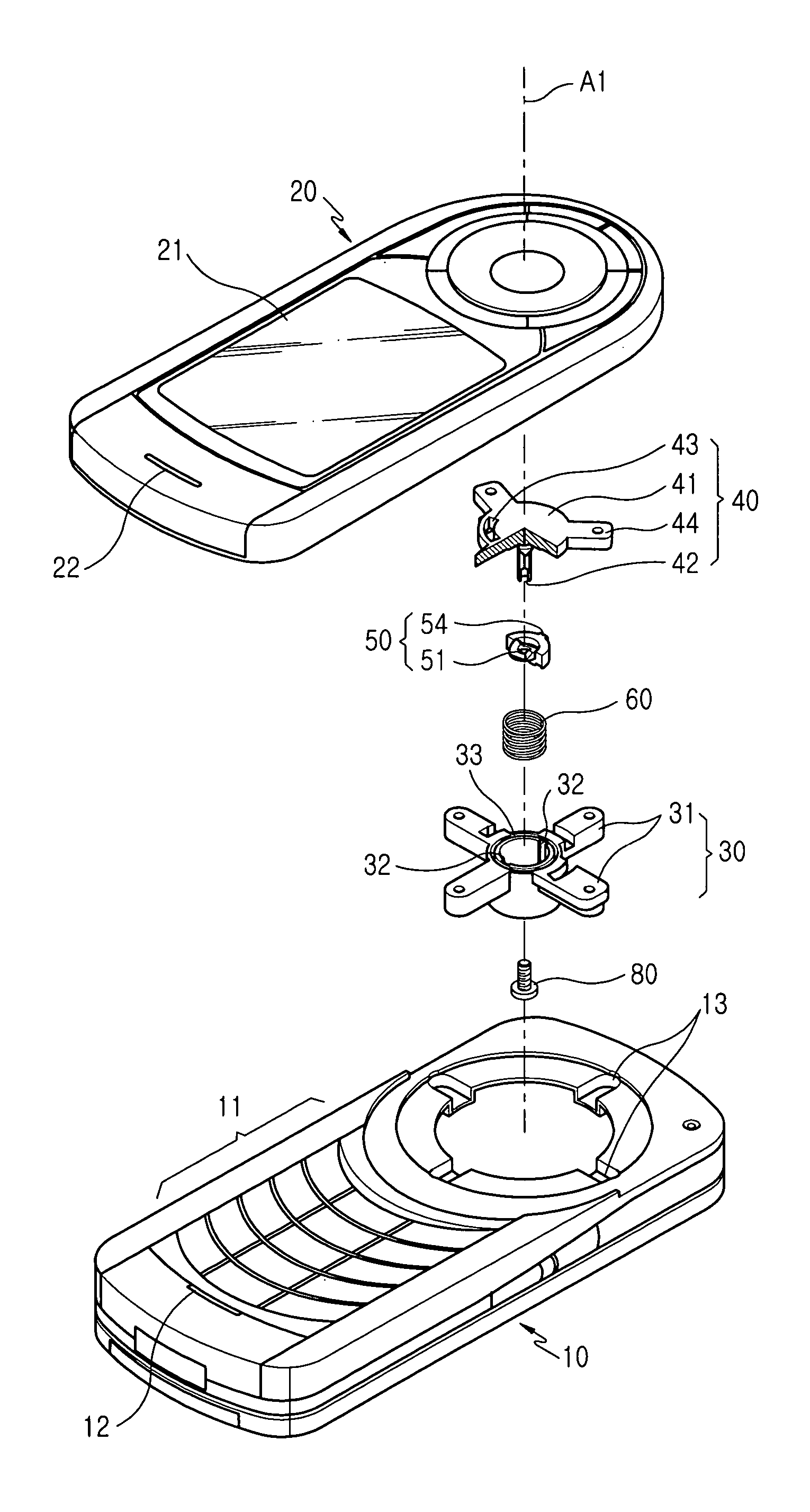
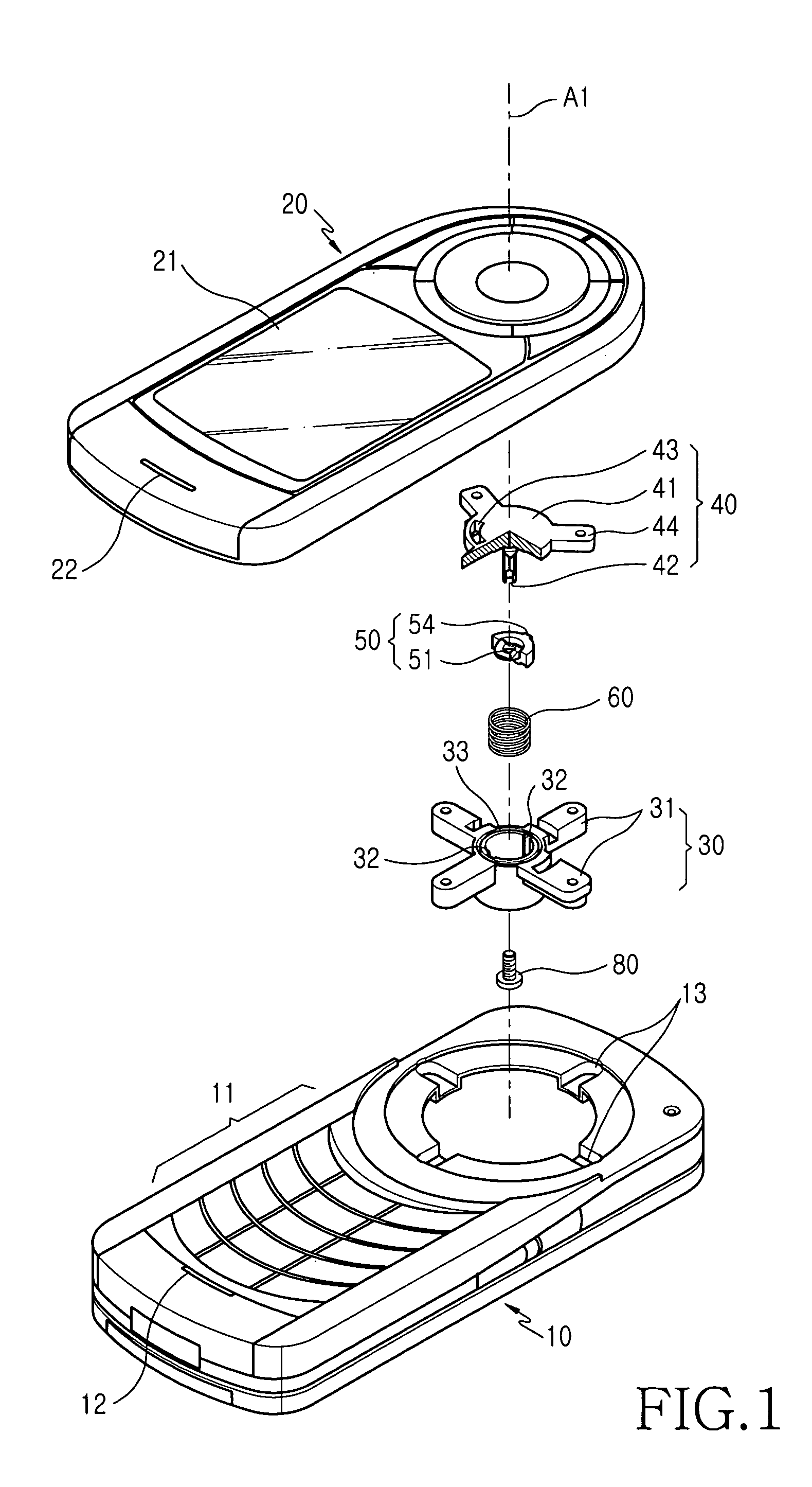
[0033]As shown in FIGS. 1 to 13, a portable terminal is provided with a first housing 10 having a number of keypads 11 and a microphone device 12.

[0034]A second housing 20 is coupled to the first housing 10 and is adapted to rotate about a hinge axis A1, which extends perpendicularly to the upper surface of the first housing 10, while facing the upper surface thereof.

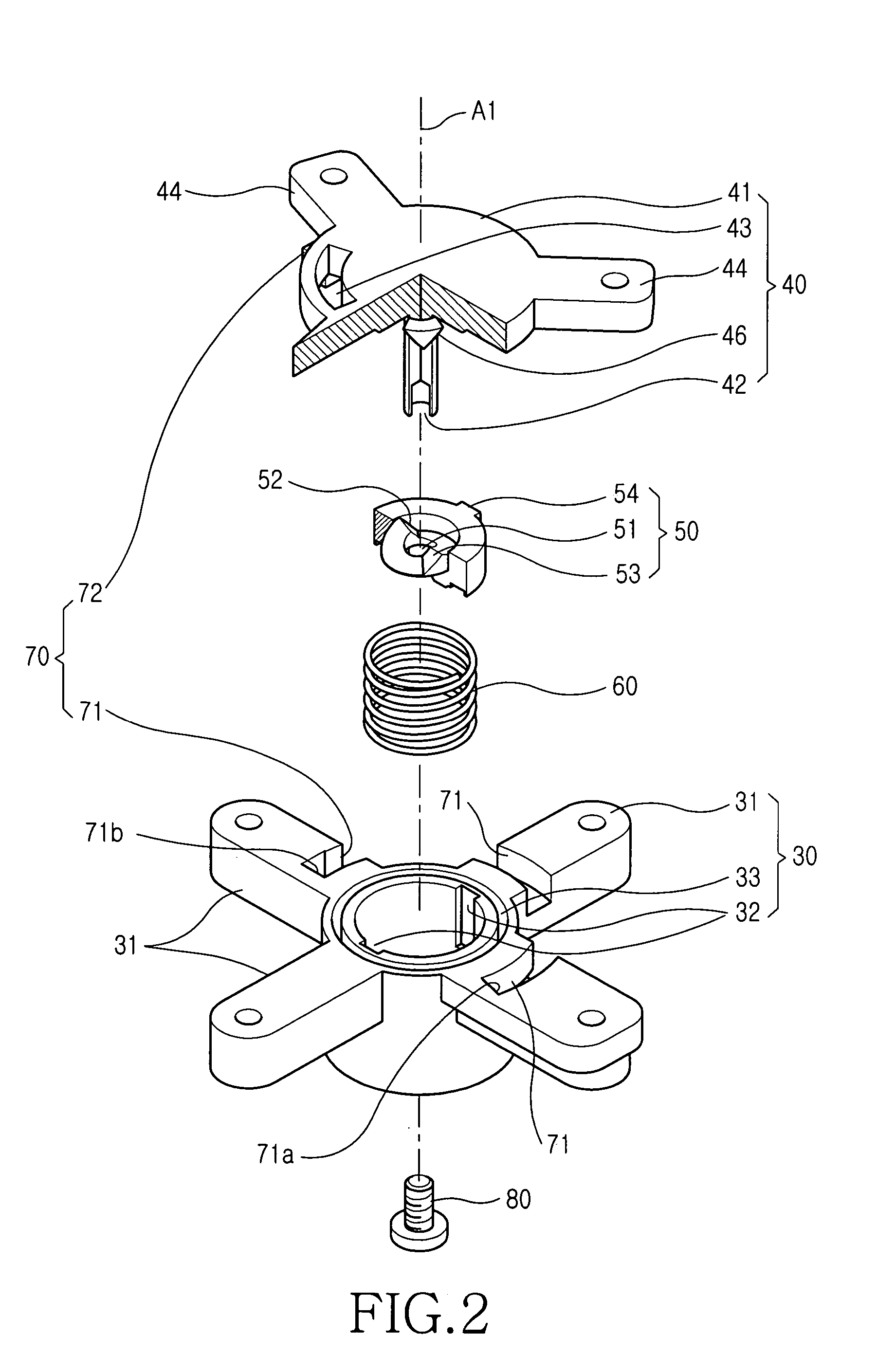
[0035]The second housing 20 is provided with a display device 21 for a display function and a speaker device 22.

[0036]A swing hinge device of the portable terminal includes a hinge housing 30, a hinge shaft 40, a hinge cam 50, a hinge spring 60, and a hinge stopper portion 70....


PUM


Abstract

A swing hinge device of a portable terminal is adapted to semi-automatically rotate a pair of housings of the terminal while they face each other to open and close them. The swing hinge device of a portable terminal having a first housing and a second housing includes a hinge housing extending along a longitudinal direction and having a reception space formed therein. A hinge shaft is rotatably coupled to the hinge housing and has a number of crests formed thereon. A hinge cam is positioned in the reception space of the hinge housing and is adapted to linearly travel therein along the longitudinal direction of the hinge axis and has a number of troughs formed thereon that face the respective crests. A hinge spring is positioned between the hinge housing and the hinge cam to provide an elastic force so that the hinge cam may linearly travel while forcing it against the hinge shaft. A hinge stopper portion is positioned between the hinge housing and the hinge shaft to limit the range of rotation of the hinge shaft that rotates in the hinge housing.

Description

CROSS REFERENCE TO RELATED APPLICATION[0001]This application claims the benefit under 35 U.S.C. § 119(a) of an application entitled “Swing Hinge Device of Portable Terminal” filed with the Korean Intellectual Property Office on Mar. 12, 2004 and assigned Ser. No. 2004-16834, the entire contents of which are hereby incorporated by reference.BACKGROUND OF THE INVENTION[0002]1. Field of the Invention[0003]The present invention relates to a swing hinge device of a portable terminal. More particularly, the present invention relates to a swing hinge device of a portable terminal adapted to semi-automatically rotate a pair of housings of the terminal while they face each other to open and close them.[0004]2. Description of the Related Art[0005]In general, a “portable communication apparatus” refers to an apparatus that a user can carry with him to perform wireless communication with a desired partner. Portable communication apparatuses include HHPs, CT-2 cellular phones, digital phones, PC...

Claims


Application Information

Patent Timeline
Patent Type & Authority Patents(United States)
IPC IPC(8): E05D11/10H04B1/38E05D5/00H01R39/00H04M1/00H04M1/02H05K7/00H05K7/16
CPCH04M1/0227H04M1/0233Y10T16/54035Y10T16/540255Y10T16/5387Y10T16/53238H04B1/38
Inventor PARK, SUNG-SUNBAE, JONG-GUN
Owner SAMSUNG ELECTRONICS CO LTD
Learn More