
Microphone cover

a microphone cover and microphone technology, applied in the direction of hearing aid sets, hearing device specific tools, electric devices, etc., can solve the problems of affecting the appearance of the coupling element on the one hand, generating additional costs, and affecting the operation of the hearing device, etc., to achieve reliable protection against dirt and humidity, easy to be removed or replaced, and easy to assemble

Active Publication Date: 2007-10-16
SONOVA AG
View PDF4 Cites 10 Cited by
  • Summary
  • Abstract
  • Description
  • Claims
  • Application Information

AI Technical Summary

Benefits of technology

[0008]It is an object of the present invention to provide a cover for openings of hearing devices, which is easy to assemble, provides a reliable protection against dirt and humidity and which is easy to be removed or replaced where required.
[0009]The present invention provides a microphone cover for hearing devices for at least partially covering openings arranged at the outside of the hearing device, comprising a ring with racks overdrawing the opening of the ring, whereby the outer diameter of the ring is nearly equivalent with the inner diameter of the corresponding opening of the hearing device, such as the ring is at least partly insertable within the opening. Thus, no connecting elements protruding from the surface of the hearing device for the attachment of the microphone cover are necessary. A high form stability of the ring is ensured by the racks, thus building a firm connection between the outside of the ring and the contact surface of the opening which is closed for dirt and / or humidity.
[0010]In one embodiment the ring consists of a substantially circular flat disk with a centrally arranged opening. The microphone cover may thus be easy inserted into the corresponding opening of the hearing device. The ring preferably consists of a tapered or rounded brink directed to the outside of the hearing device in its fitted state. This is an optimal shape to the outside of the hearing device, preventing dirt of being anticipated or deposited at this area.

Problems solved by technology

The involved hearing devices will subsequently have to be cleaned or the microphone will have to be replaced, which may as a rule only be performed by skilled professionals and generate additional costs.
The reduction or failure of the microphones will be appreciated as low quality of the overall hearing device and thus constitute a bad image of the hearing devices concerned.
Such a coupling element may on one hand be optically disturbing and on the other hand be susceptible for the collection of dirt due to its edges.
Such a cap furthermore risks to unintentionally or independently loosen and thereby will get lost or intrudes into the ear canal.
This covering provides only small form stability and may therefore build up a gap between the cover and the opening susceptible for dirt and humidity.
A disadvantage of this construction lies in the fact that the plug may practically no longer be removed out of the opening or the channel.
A further problem relates to the possibility of pushing the plug too far into the opening or channel respectively, thereby forming again an open chamber susceptible for the deposition of dirt and thus closing the respective openings.

Method used


Image

  • Microphone cover
  • Microphone cover
  • Microphone cover

Examples


Embodiment Construction

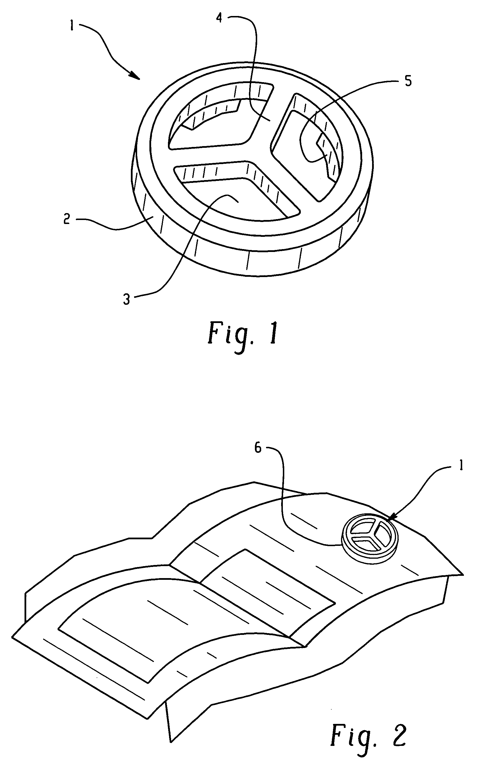
[0039]Referring to FIG. 1, an inventive microphone cover 1 is shown. It consists essentially of a ring 2 with racks 4 directed to the center and connected together in the center of ring 2 such as spokes of a wheel. Openings 3 are formed between the ring 2 and the racks 4. The ring 2 and the racks 4 are for instance provided as a single piece element and consist of plastic. Such an element may be easy and cost effective manufactured as an injection molded element.

[0040]The racks 4 are curved convex to the centre of the ring 2 and therefore adapted to the contour of the hearing device, as shown in FIG. 2.

[0041]The microphone cover 1 is inserted into the opening 6 of the hearing device, whereby the upper edge of the ring 2 is slightly protruding to the outside or closes firm with the surface of the hearing device in this area. The exact position of the microphone cover 1 is achieved by a stop provided within the opening 6 at a predetermined depth. Thus, the microphone cover 1 may not b...


PUM


Abstract

The inventive microphone cover for hearing devices for at least partially covering openings (6) arranged at the outside of the hearing device comprises a ring (2) with racks (4) overdrawing the opening of the ring (2). The outer diameter of the ring (2) thereby is equivalent with the inner diameter of the corresponding opening (6) of the hearing device such as the ring (2) is at least partly insertable within the opening (6). A stop (11) is provided advantageously within the opening (6) at a desired depth (t) to define the exact insertion position of the microphone cover (1).

Description

BACKGROUND OF THE INVENTION[0001]This invention relates to a Microphone cover for hearing devices for at least partially covering openings arranged at the outside of the hearing devices and to a hearing device with openings arranged at the outside of the hearing device with a microphone cover.[0002]It is to be noted that the term hearing devices shall cover as well hearing aids, such as behind-the-ear hearing aids and in-the-ear hearing aids.[0003]Hearing devices comprise at least one microphone for the receiving and amplification or eventually reduction of sound events. This microphone is exposed to different environmental influences, such as humidity, sweat and cerumen. Actuating elements such as switches or volume controls are arranged in the direct vicinity of the microphones of miniaturized hearing devices, such as in-the-ear hearing-aids. Dirt in form of particles may thus be disposed by the fingers of the wearer of the hearing device in the area of the microphone opening. Thi...

Claims


Application Information

Patent Timeline
Patent Type & Authority Patents(United States)
IPC IPC(8): H04R25/00
CPCH04R25/00H04R1/12H04R2460/17
Inventor KARAMUK, ERDAL
Owner SONOVA AG
Learn More