
Method and device for short circuit or open load detection

a short circuit and detection method technology, applied in emergency protective arrangements for limiting excess voltage/current, instruments, emergency protective arrangements for automatic disconnection, etc., can solve problems such as continuous energy loss, device described in the above document is not able, and inability to distinguish between open load and short circuit condition

Active Publication Date: 2007-10-09
AMI SEMICON BELGIUM
View PDF6 Cites 32 Cited by
  • Summary
  • Abstract
  • Description
  • Claims
  • Application Information

AI Technical Summary

Benefits of technology

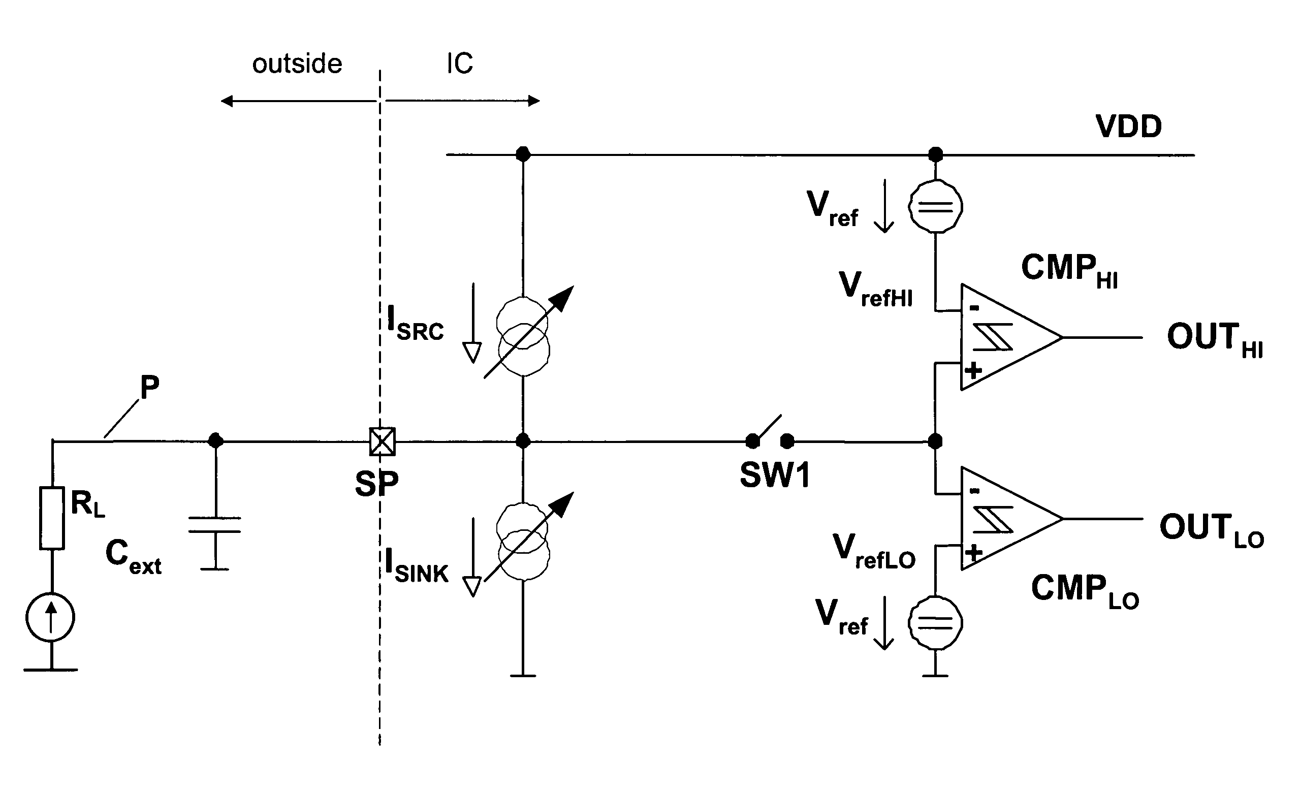
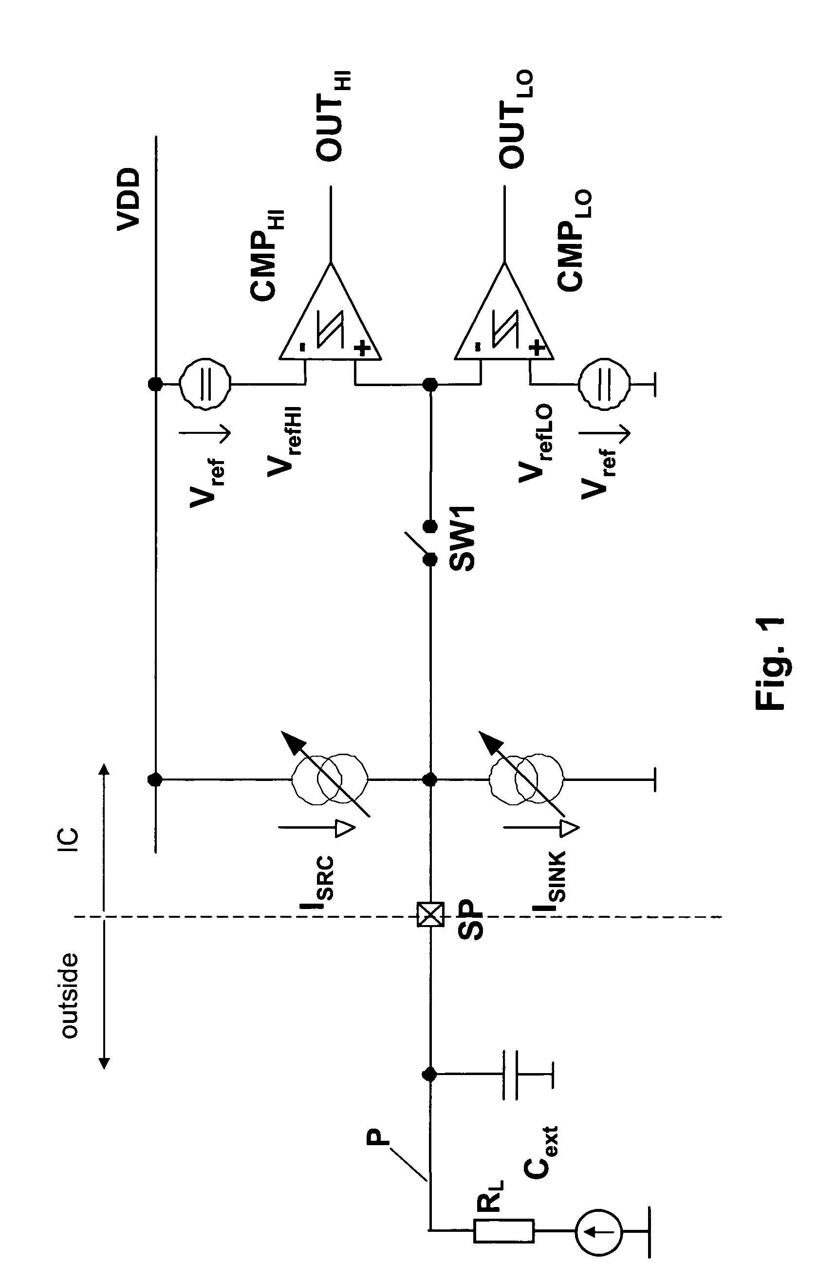
"The present invention provides a method and device for detecting error conditions in a load or connection to a load. The method involves determining whether the load and connection are in a normal operation condition or an error condition, and if an error condition is present, determining whether it is an open load condition, a short circuit condition to ground or a short circuit condition to power supply. The method includes monitoring parameters associated with the load, such as voltage or current, and changing the first parameter to escape from the error condition. The apparatus includes first diagnosis means for determining the error condition and second diagnosis means for changing the first parameter to escape from the error condition. The resetting means may also be used to reset the load to the starting state. The technical effect of the invention is to provide a more accurate and effective method and device for detecting and addressing error conditions in a load or connection."

Problems solved by technology

Some of those are not able to distinguish between open load and short circuit condition.
The device described in the above document is not able, once a short circuit condition has been detected, to distinguish between short circuit to battery or short circuit to ground.
One disadvantage, however, of the method described in WO 92 21985 is that a resistor is permanently taking current , which results in a continuous energy loss.

Method used


Image

  • Method and device for short circuit or open load detection
  • Method and device for short circuit or open load detection
  • Method and device for short circuit or open load detection

Examples


Embodiment Construction

[0038]The present invention will be described with respect to particular embodiments and with reference to certain drawings but the invention is not limited thereto but only by the claims. The drawings described are only schematic and are non-limiting. In the drawings, the size of some of the elements may be exaggerated and not drawn on scale for illustrative purposes.

[0039]The terms first, second, third and the like in the description and in the claims, are used for distinguishing between similar elements and not necessarily for describing a sequential or chronological order. It is to be understood that the terms so used are interchangeable under appropriate circumstances and that the embodiments of the invention described herein are capable of operation in other sequences than described or illustrated herein.

[0040]It is to be noticed that the term “comprising”, used in the claims, should not be interpreted as being restricted to the means listed thereafter; it does not exclude oth...


PUM


Abstract

A method or apparatus is provided for detecting an error condition associated with a load (RL) or a connection (P) to the load (RL). The load (RL) may comprise an energy storing element (Cext). During a first diagnosis phase, it is determined whether the load (RL) or the connection (P) to the load (RL) is in a normal operation condition or in an error condition. If the load (RL) or the connection (P) to the load (RL) is in an error condition, during a second diagnosis phase it is determined whether the error condition is an open load condition, short circuit condition to ground or a short circuit condition to a power supply. When the load is in a starting state before the first diagnosis phase, the method or apparatus may further comprise carrying out, after the second diagnosis phase, a resetting phase for resetting the load to the starting state.

Description

TECHNICAL FIELD OF THE INVENTION[0001]The present invention relates to methods and circuits for detecting error conditions such as open load or short circuit conditions on a pin.BACKGROUND OF THE INVENTION[0002]Several types of circuits used for detecting open load or short circuit condition on a pin exist. Some of those are not able to distinguish between open load and short circuit condition.[0003]U.S. Pat. No. 4,962,350 describes an automatic load condition detection system for detection of a normal or abnormal load condition. The system described distinguishes between short circuit condition and open load condition. A two-phase measurement is used. During a first phase, a load current is supplied to a load from a power source device. In a first phase, a discrimination is made between an abnormal operating condition with the load in an open circuit condition, and another operating condition. If, during the first phase, it is detected that the load is not in an open circuit condit...

Claims


Application Information

Patent Timeline
Patent Type & Authority Patents(United States)
IPC IPC(8): H02H3/00H02H3/087H02H3/12
CPCH02H3/12H02H3/087
Inventor HORSKY, PAVELKOUDAR, IVAN
Owner AMI SEMICON BELGIUM
Learn More