
Method for controlling oil and gas well production from multiple wells

Inactive Publication Date: 2007-09-25
SUPERIOR ENERGY SERVICES LLC
View PDF14 Cites 25 Cited by
  • Summary
  • Abstract
  • Description
  • Claims
  • Application Information

AI Technical Summary

Benefits of technology

This solution increases oil and gas production efficiency by allowing wells to produce more frequently, reducing well loading, and minimizing the need for costly human intervention, while ensuring that all wells can operate at their capacity without overloading the sales line.

Problems solved by technology

Once the pressure switch trips, and stays tripped during the filter time, the controller starts the spike delay period, which will delay any attempt to open the motor valve as a result of the pressure switch being tripped.

Method used


Image

  • Method for controlling oil and gas well production from multiple wells
  • Method for controlling oil and gas well production from multiple wells
  • Method for controlling oil and gas well production from multiple wells

Examples


Embodiment Construction

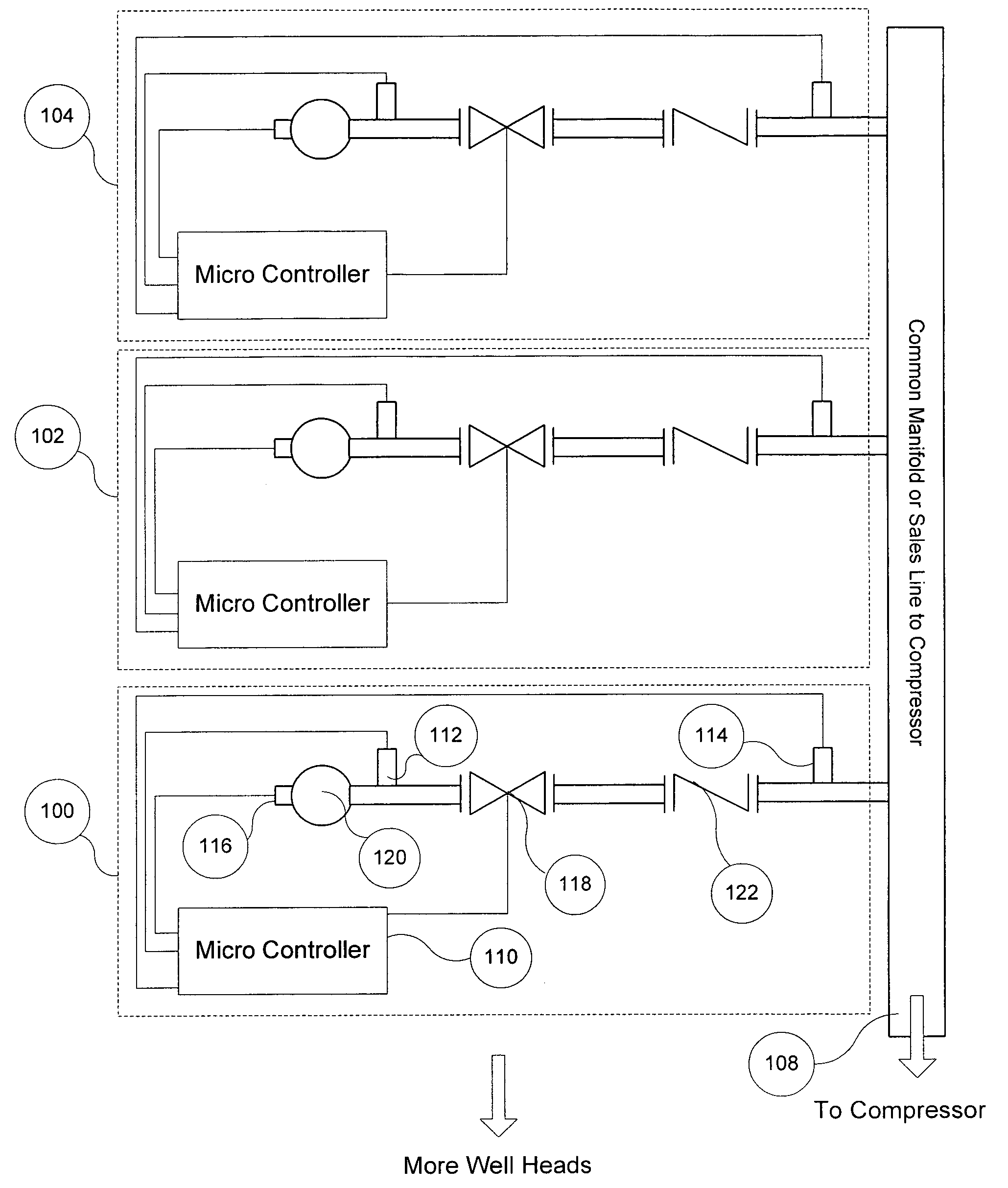
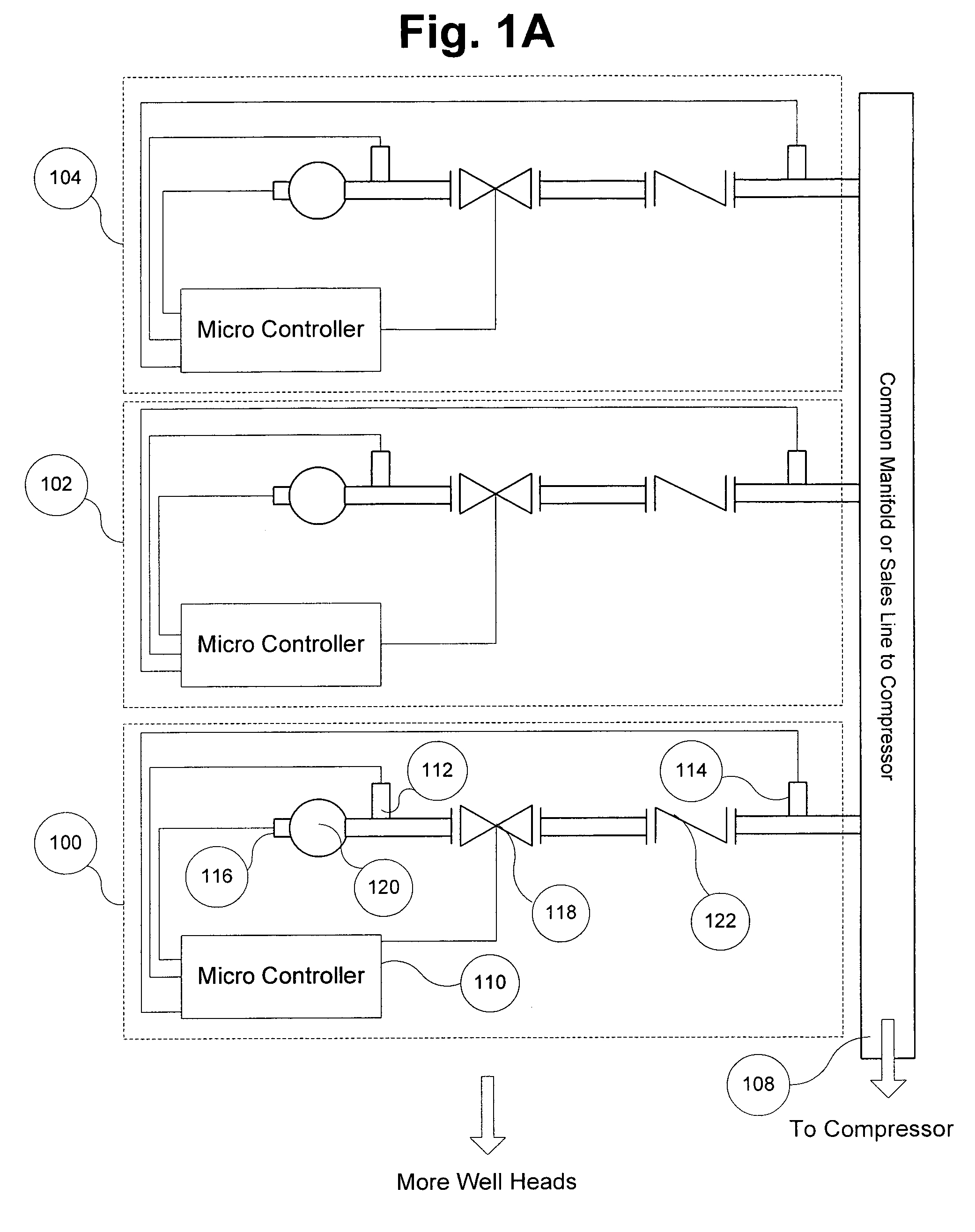
[0019]In the preferred embodiment, the micro controller is a differential pressure controller such as the one presented in pending patent application Ser. No. 10 / 298,499, published application number U.S. 2003-0145986 A1, and uses two pressure transducers, a plunger arrival sensor, a plunger and a motor valve to control the well production rate and timing.

[0020]Referring now to FIG. 1A, a system according to the present invention comprises three identical connecting subsystems 100, 102, and 104 that connect three wells to a common sales line 108. The system is not limited to servicing three wells. Rather, the system can handle two or more wells that are attached to a common sales line 108.

[0021]The subsystem 100 includes a micro controller 110, two pressure transducers 112 and 114, a plunger detector 116, a motor valve 118, a well head 120, a check valve 122 and additional equipment associated with any product recovery operation that uses a plunger lift system.

[0022]The micro contro...


PUM


Abstract

A method for producing oil or gas from multiple wells, the wells including at least a first well and a second well, with each well using an artificial lift system that includes a plunger associated with a motor valve off time, and first and second identical connecting subsystems that connect their respective wells to a common sales line. The first connecting subsystem includes: a) a plunger arrival sensor connected to a micro controller; b) a wellhead connected to the first well; c) a motor valve connected to the wellhead; d) first and second pressure transducers on either side of the motor valve, conductively coupled to the micro controller; and e) a micro controller for keeping the motor valve closed during the motor valve off time, and extending the motor valve off time following a determination of the existence of a pressure spike in the common sales line.

Description

CROSS-REFERENCES TO RELATED APPLICATIONS[0001]This application claims the benefit of the following U.S. Provisional Application No. 60 / 545,076, filed Feb. 17, 2004.STATEMENT REGARDING FEDERALLY SPONSORED RESEARCH OR DEVELOPMENT[0002]Not applicable.REFERENCE TO A “SEQUENTIAL LISTING.”[0003]Not applicable.BACKGROUND OF THE INVENTION[0004]1. Field of the Invention[0005]The present invention relates to control of oil or gas well production in the latter stages of well life and, more particularly, to a device and method for controlling the action of a cluster of oil and or gas wells that are sharing a production line or sales line while using a plunger lift system or an oil lift system; generally, any artificial lift system.[0006]2. Description of the Related Art[0007]In many oil and gas well fields with artificial lift system production installations the well flow lines or sales lines are connected through a common manifold. Flow lines, sales lines and the common manifold are all interc...

Claims


Application Information

Patent Timeline
Patent Type & Authority Patents(United States)
IPC IPC(8): E21B43/12G05D7/00
CPCE21B43/12Y10T137/2567
Inventor EVANS, RICKOEHLERT, MICHAEL A.PUGH, TREVOR
Owner SUPERIOR ENERGY SERVICES LLC
Learn More