
Repetitive visual stimulation to EEG neurofeedback protocols

a neurofeedback and visual stimulation technology, applied in the field of repetitive visual stimulation to eeg neurofeedback protocols, can solve the problems of affecting the accuracy of the final evoked potential estimate, difficult measurement of sensory evoked potentials, and inability to provide a suitable means of studying dynamic changes in brain activity

Active Publication Date: 2007-09-11
COLLURA THOMAS F
View PDF8 Cites 28 Cited by
  • Summary
  • Abstract
  • Description
  • Claims
  • Application Information

AI Technical Summary

Benefits of technology

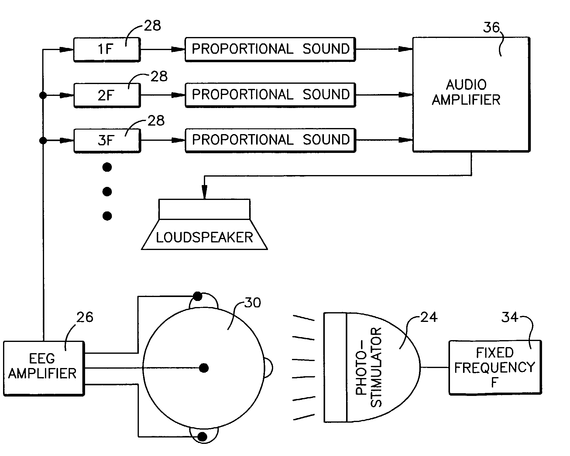
[0019]In a particular embodiment of the invention, there is provided a method of measuring sensory and perceptual mechanisms and training these pathways with feedback. The method is basically the same as above, with the addition of the total evoked brain activity being reconstructed by combining the filter outputs. This evoked response can then be fed back, in real-time, to the subject. Thus, the feedback reflects the brain's response to the repetitive stimulation, and allows the subject to receive real-time feedback regarding their current state of attention.

Problems solved by technology

However, an alternative interpretation is possible when study is limited to the responses to discrete stimuli such as brief clicks or flashes.
However, sensory evoked potentials are—difficult to measure because they represent the activity of only a small portion of the cells producing surface potentials, and are thus buried in background EEG noise.
Since ongoing brain processes may produce evoked potential changes in mere seconds, averaging does not provide a suitable means of studying dynamic changes in brain activity.
On the contrary, such changes introduce signal variance which further degrades the accuracy of the final evoked potential estimate.
However, this technique has only been explored from a purely psychophysical standpoint; its application to cognitive monitoring is as of yet unexplored.

Method used


Image

  • Repetitive visual stimulation to EEG neurofeedback protocols
  • Repetitive visual stimulation to EEG neurofeedback protocols
  • Repetitive visual stimulation to EEG neurofeedback protocols

Examples


Embodiment Construction

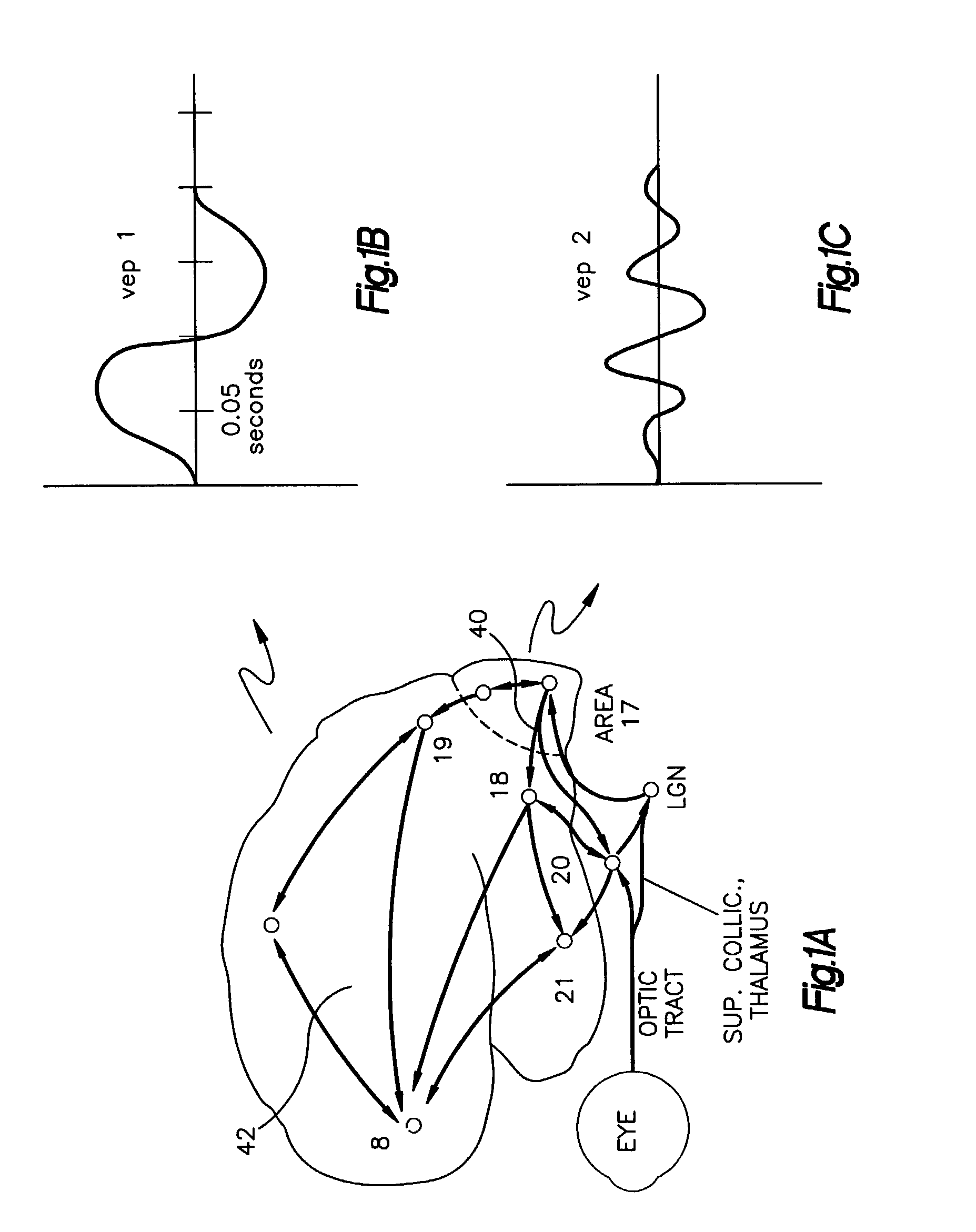
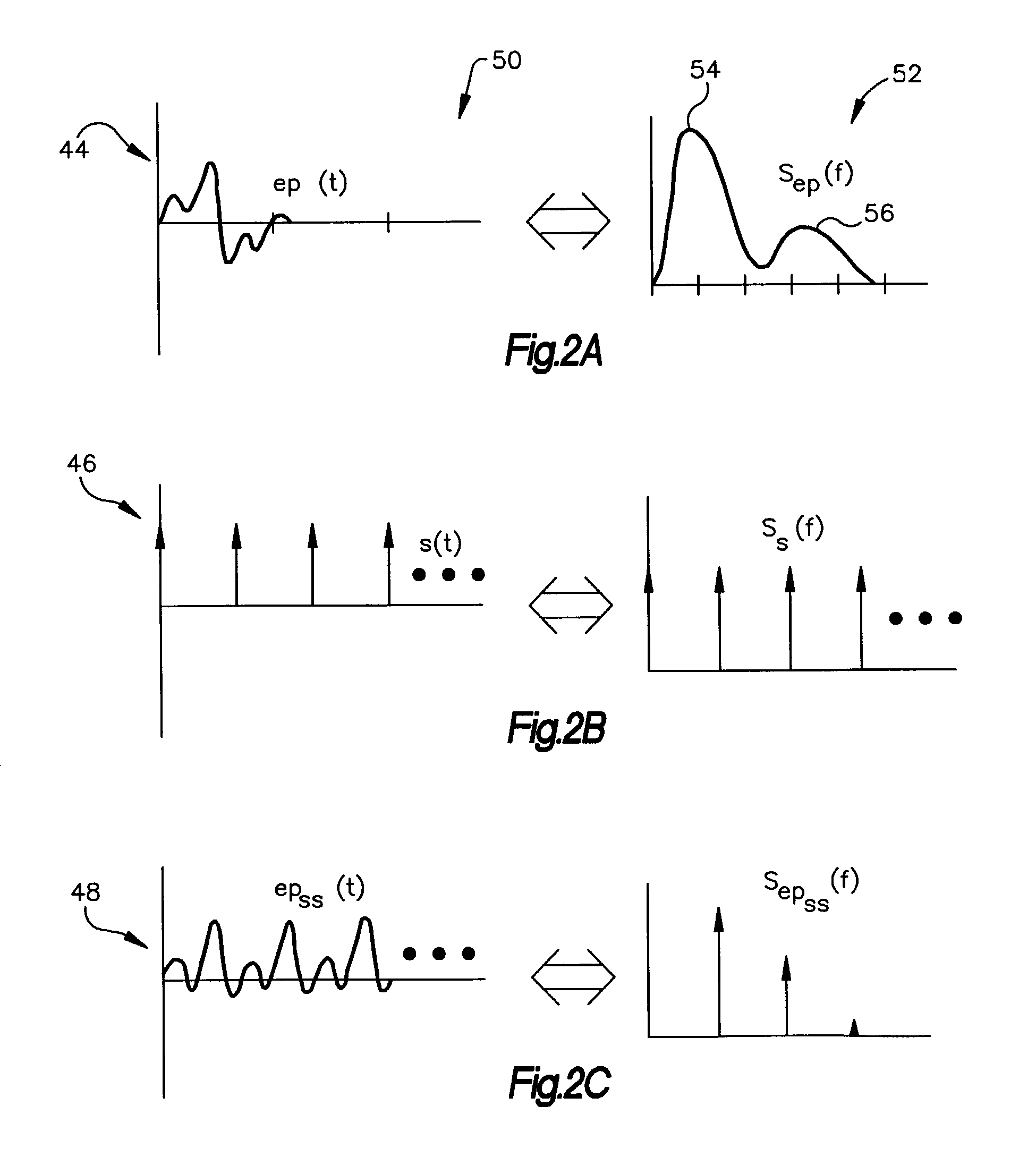
[0031]The present invention provides a method of measuring evoked potentials in response to sensory / perceptual processes. Repetitive stimulation introduces a periodic evoked response in the EEG that can be measured and fed back in real time. The EEG response to repetitive stimulation can be described as a series of successive evoked potentials (EP), giving rise to a periodic response in the cortex, referred to as the steady-state visual evoked potential (SSVEP). The method is especially advantageous in that experimental data collected shows that short-term variations in signal amplitude are shown to be sensitive to short-term shifts in attention, and to reveal moment-to-moment changes in brain responsiveness.

[0032]FIG. 1A depicts the neuroanatomical pathways involved in the response of the human brain to a light flash. When neural activity first reaches the visual cortex 40, the early components of the visual evoked potential are produced. As activity diffuses in the cortex and reac...


PUM


Abstract

An EEG neurofeedback and total evoked brain activity measurement methods utilize minimum ambient EEG activity as stimulant frequencies. A method of using repetitive stimulation in conjunction with EEG neurofeedback protocols is described. Electrodes, attached to a subject's scalp, transmit electroencephalographic (EEG) signals from the subject. These signals are in response to the visual and / or auditory stimuli being displayed to the subject. The resultant EEG signals are then filtered at pre-defined frequencies or frequency bands. The output from the filtered EEG signals is then analyzed and monitored for short-term state changes. The invention also uses flicker stimulation, real-time signal filtration and feedback, feedback during audio and visual stimulation derived from filtered outputs, and fundamental and integral harmonics in combination with total evoked response.

Description

FILED OF THE INVENTION[0001]The present invention relates generally to a method for studying dynamic sensory brain processes, and more particularly, to a method for using repetitive visual and / or auditory stimulation in the context of EEG neurofeedback protocols.BACKGROUND OF THE INVENTION[0002]The origin and nature of brain waves as measured from the human scalp has been a topic of ongoing research. For example, the electroencephalogram (EEG) as measured from the intact human scalp is of interest in psychology and psychophysics because it can provide an indication of the activity of brain cells in the awake, alert state. Of particular use are the minute potentials evoked by sensory stimuli, for these time-locked transient wavelets show how populations of cells behave in response to afferent volleys carried by primary sensory fibers.[0003]Whenever a brief stimulus is presented to a trainee, there is a transient brain response due to that stimulation. The signal produced in the EEG i...

Claims


Application Information

Patent Timeline
Patent Type & Authority Patents(United States)
IPC IPC(8): A61B5/04A61B5/375
CPCA61B5/0482A61B5/04842A61B5/04845Y10S128/905A61B5/375A61B5/38A61B5/378
Inventor COLLURA, THOMAS F.
Owner COLLURA THOMAS F
Learn More