
High isolation tunable MEMS capacitive switch

a capacitive switch, high isolation technology, applied in relays, generators/motors, snap-action arrangements, etc., can solve the problems of poor isolation at frequencies below 10 ghz, preventing capacitive switches from being employed in most commercial applications, and x-band switches only achieve improved isolation, and it is difficult to further lower the resonant frequency to c-band frequencies

Active Publication Date: 2007-09-04
RGT UNIV OF CALIFORNIA
View PDF1 Cites 15 Cited by
  • Summary
  • Abstract
  • Description
  • Claims
  • Application Information

AI Technical Summary

Problems solved by technology

However, because resistive switches rely on multiple metallic surfaces in contact with each other during current passage, microwelding and stiction become significant drawbacks of resistive switch implementation.
Although capacitive RF MEMS switches have advantages over resistive switches in the amelioration of microwelding and stiction issues, the isolation of capacitive switches tends to be fair (˜20 dB) at 10-25 GHz and poor (˜10 dB) below 10 GHz.
This poor isolation at frequencies below 10 GHz precludes capacitive switches from being employed for most commercial applications.
However, these X-Band switches only achieve improved isolation in the 10+ to 12 GHz frequency range because it becomes very difficult to further lower the resonant frequency to C-band frequencies due to the impractically large inductance required.
To sufficiently increase the inductance requires a shape change of conductive line and brings in discontinuity for the waveguide, which requires difficult design compensations.

Method used


Image

  • High isolation tunable MEMS capacitive switch
  • High isolation tunable MEMS capacitive switch
  • High isolation tunable MEMS capacitive switch

Examples


Embodiment Construction

[0026]The systems and methods described herein provide for an RF MEMS capacitive switch capable of wideband tuning at low frequencies with high isolation. In a preferred exemplary embodiment, the switch operates in a CPW mode having a first resonant frequency and a coupled slotline (CSL) mode having a second, lower resonant frequency. The second resonant frequency position can be controlled by adjusting the inductance of the transmission line and / or the capacitance of the switch. The second resonant frequency, in one exemplary embodiment, can be in the range of 2-10 Ghz, which is a range suitable for use in many commercial wireless applications.

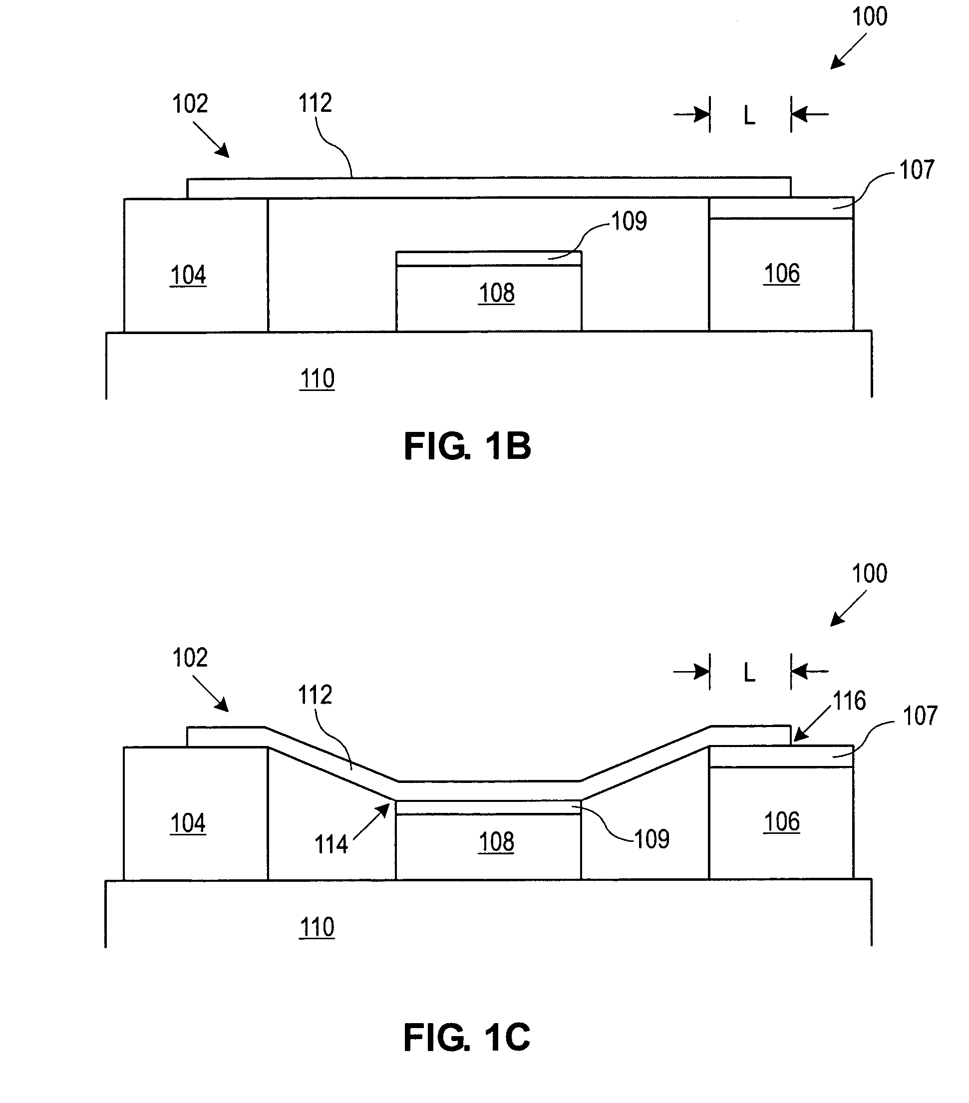
[0027]FIGS. 1A-D depict exemplary embodiments of RF MEMS system 100 including the capacitive switch 102 and two mode conversion members 120 and 122. Here, the switch 102 has a first electrode 104, a second electrode 106 and a conductive line 108 located on a substrate 110. The second electrode 106 and the conductive line 108 are each covered ...


PUM

PropertyMeasurementUnit
resistanceaaaaaaaaaa
up-state capacitanceaaaaaaaaaa

Abstract

The systems and methods described herein provide for a radio frequency micro-electromechanical systems switch having two or more resonant frequencies. The switch can be configured as a capacitive shunt switch having a deflectable member coupled between two electrodes over a transmission line. A first insulator can be located between one of the electrodes and the deflectable member to form a capacitive element. The deflectable member can be deflectable between an up-state and a down-state, the down-state capacitively coupling the deflectable member with the transmission line. The degree by which the deflectable member overlaps the first insulator can be adjusted to adjust the capacitance of the capacitive element and the resulting resonant frequency.

Description

CROSS-REFERENCE TO RELATED APPLICATIONS[0001]This application claims priority to U.S. provisional application Ser. No. 60 / 552,906, filed Mar. 12, 2004, which is fully incorporated herein by reference.FIELD OF THE INVENTION[0002]The systems and methods described herein relate generally to micro-electromechanical systems (MEMS) and, more particularly, to a MEMS capacitive switch that facilitates high isolation wideband tuning.BACKGROUND INFORMATION[0003]Radio frequency micro-electromechanical system (RF MEMS) switches are basic building blocks for construction of various RF components and sub-systems such as variable capacitors, phase shifters, tunable RF matching circuits / filters, and reconfigurable antennas, to name a few. RF MEMS switches can be classified in two general groups based on their electrical contact methods: 1) metal-to-metal ohmic (or DC) contact switches, known as resistive series switches, and 2) capacitive contact switches, known as capacitive shunt switches. The re...

Claims


Application Information

Patent Timeline
Patent Type & Authority Patents(United States)
IPC IPC(8): H01P1/10B81B5/00H01H59/00
CPCH01H59/0009H01G5/16H01G5/40H01H2001/0084Y10T29/49002Y10T29/49155Y10T29/49117Y10T29/49128Y10T29/49156Y10T29/49105
Inventor QIAN, JIANGYUANCHANG, HUNG-PINCETINER, BEDRI A.BACHMAN, MARKDEFLAVIIS, FRANCOLI, GUANN-PYNG
Owner RGT UNIV OF CALIFORNIA
Learn More