
Electrical motor and fluid pump using the same

a technology of electric motors and fluid pumps, applied in the direction of liquid fuel engines, magnetic circuit rotating parts, magnetic circuit shapes/forms/construction, etc., can solve the problems of difficult to reduce the and achieve the effect of reducing the number of assembling steps of the rotor

Active Publication Date: 2007-09-04
AISAN IND CO LTD
View PDF22 Cites 10 Cited by
  • Summary
  • Abstract
  • Description
  • Claims
  • Application Information

AI Technical Summary

Benefits of technology

The present invention provides an electrical motor with a reduced number of assembly steps of the rotor. The motor includes a magnetic member and a rotor with coils and a connection terminal for electrically connecting the coils. The cover of the rotor is attached to the armature to form a structure member through which the connection terminal is electrically connected to the coils. This structure member reduces the number of assembly steps of the rotor. The cover is attached to the armature to prevent it from being removed, and the coils have coil terminals that are inserted into the terminal portions of the connection terminal to facilitate electrical connection. The motor can be used for a fluid pump, such as a fuel pump, with an insulation material on the pump casing and a metal cover for better heat dissipation.

Problems solved by technology

However, in this fuel pump, because the component number of the rotor is increased, it is difficult to reduce assembling steps of the rotor.

Method used


Image

  • Electrical motor and fluid pump using the same
  • Electrical motor and fluid pump using the same
  • Electrical motor and fluid pump using the same

Examples


Embodiment Construction

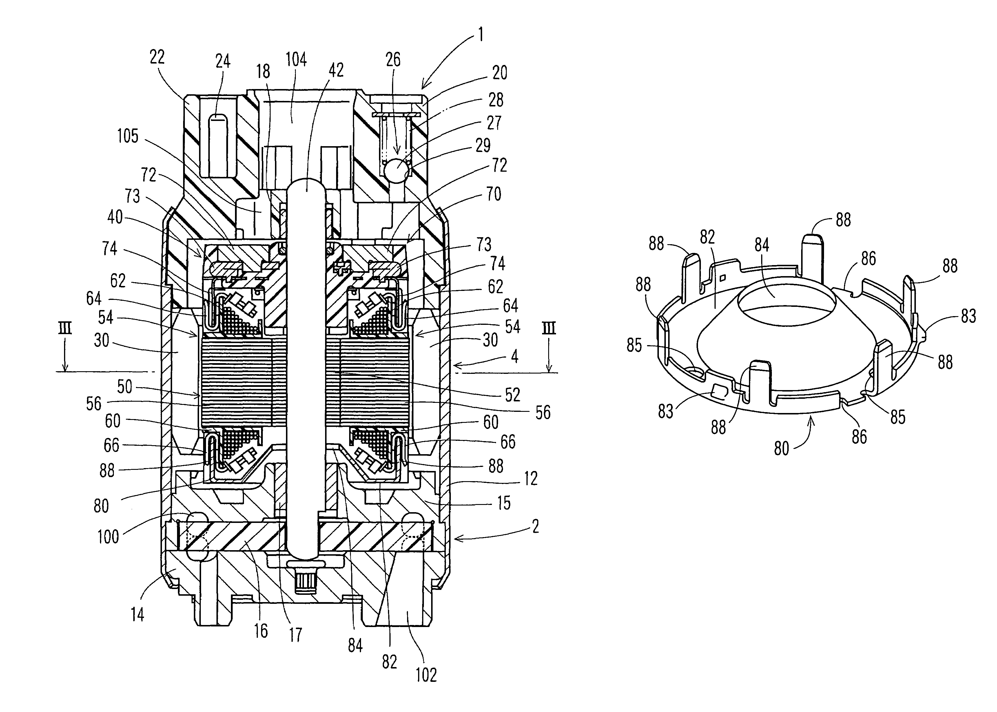
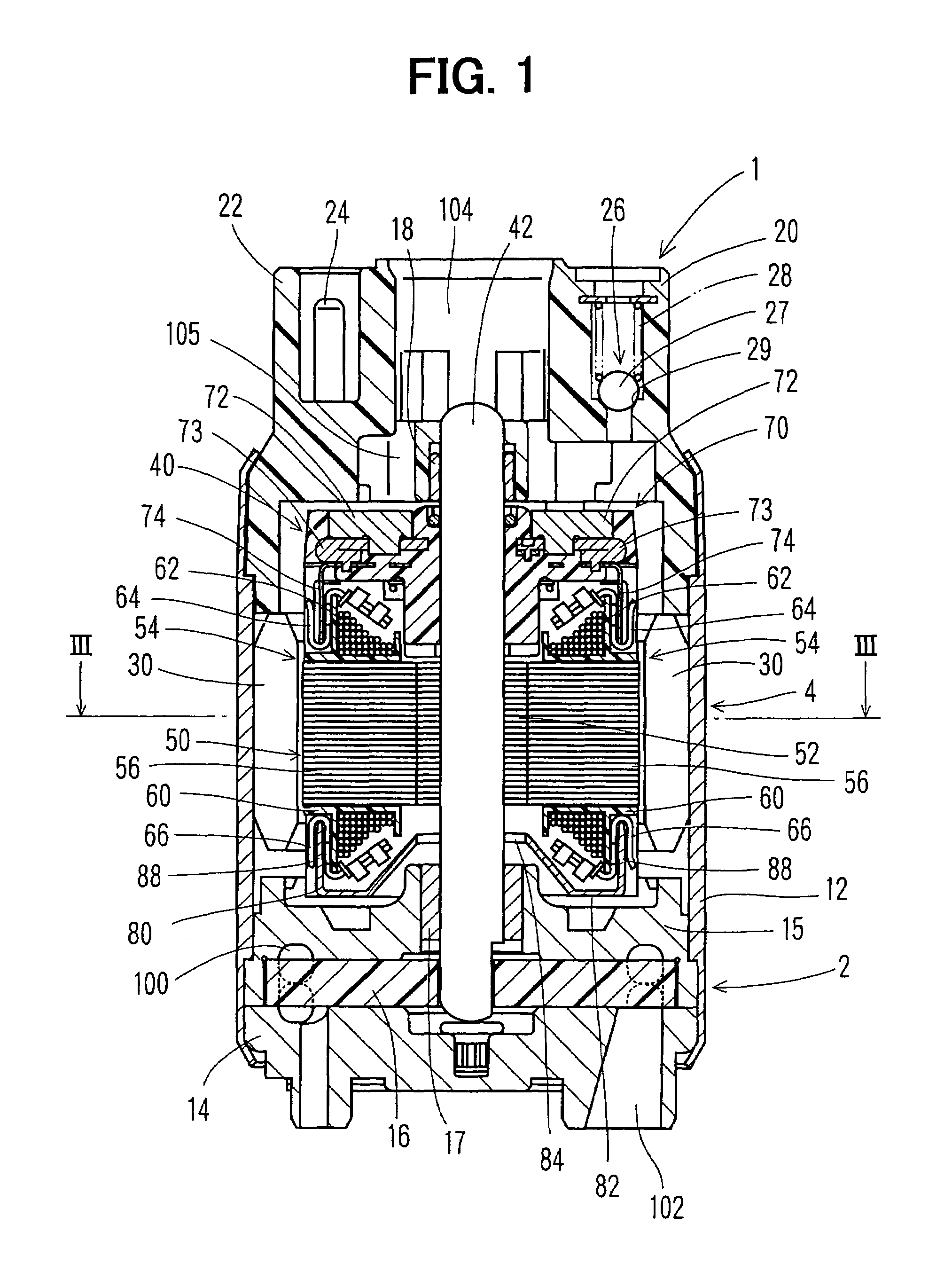
[0026]A preferred embodiment of the present invention will be now described with reference to the accompanying drawings. FIG. 1 shows a fuel pump 1 having a rotor 40 of an electrical motor 4 of the present invention. For example, the fuel pump 1 is an in-tank pump that is mounted in a fuel tank of a vehicle to supply fuel in the fuel tank to a fuel consumption system such as an engine. The fuel pump 1 includes a pump portion 2 for increasing pressure of a drawn fuel, and the electrical motor 4 for driving the pump portion 2 by rotating the rotor 40 around a shaft 42. The pump portion 2 includes an intake side cover 14, an impeller casing 15 and a circular impeller 16. The electrical motor 4 is constructed with a direct current motor, and is provided with permanent magnets 30 and the rotor 40.

[0027]A housing 12 of the fuel pump 1 fastens the intake side cover 14 and a discharge side cover 20, which are disposed at two end sides of the shaft 42 of the rotor 40. The intake side cover 1...


PUM


Abstract

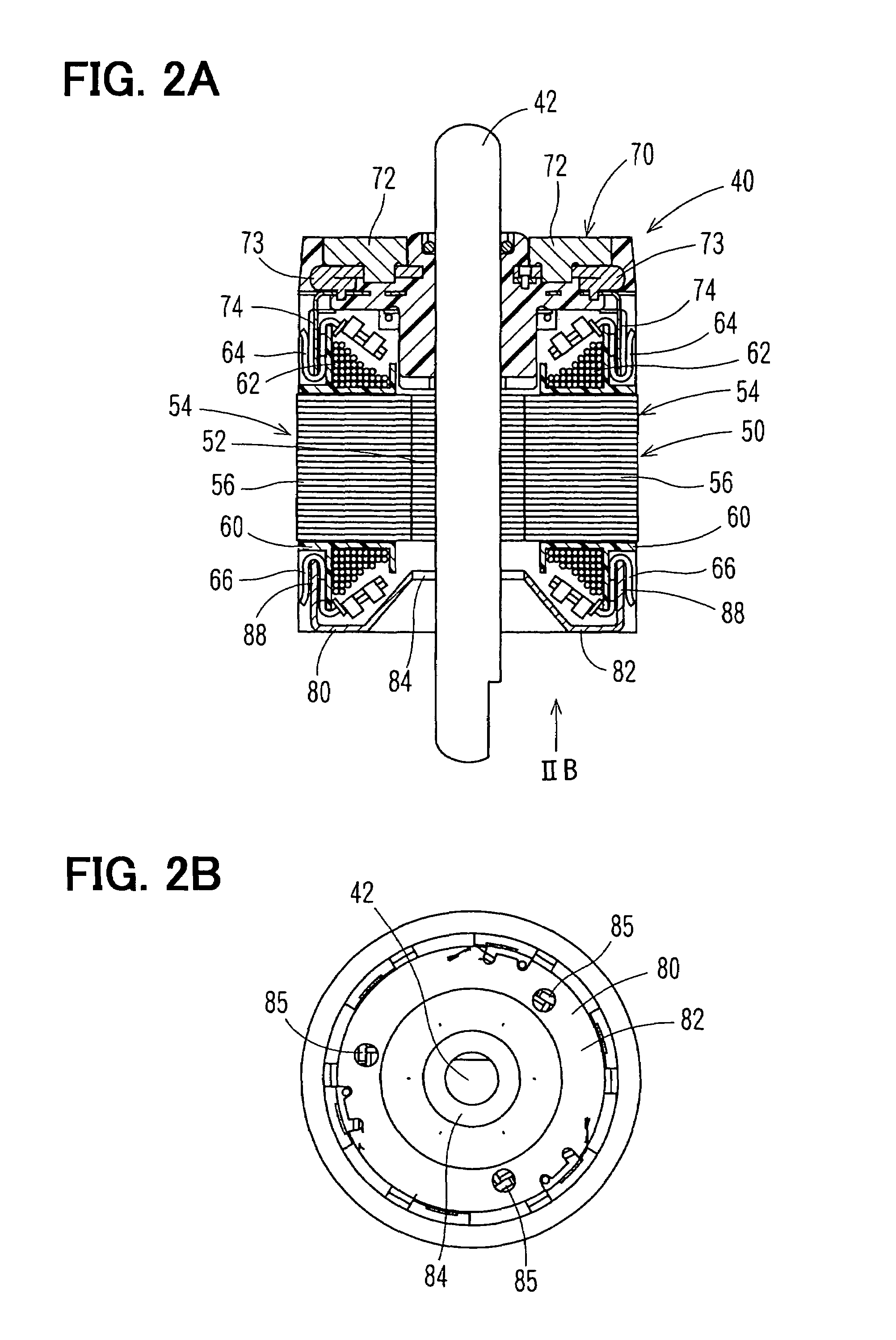
An electrical motor includes a commutator attached to one side of an armature in an axial direction, and a cover structure member attached to the other side of the armature. The cover structure member includes a cover and plural terminals protruding from an outer peripheral portion of the cover toward the armature. In the electrical motor, by attaching the cover structure member to the armature, the other side of the armature in the axial direction is covered by the cover, and the terminals of the cover structure member are fitted to terminals of coils of the armature. Generally, the cover structure member is made of metal. Therefore, the cover structure member is attached to the armature to have a clearance between a through hole portion of the cover and a shaft, so that the cover is electrically insulated from the shaft.

Description

CROSS REFERENCE TO RELATED APPLICATION[0001]This application is based on Japanese Patent Application No. 2004-006965 filed on Jan. 14, 2004, the contents of which are incorporated herein by reference.FIELD OF THE INVENTION[0002]The present invention relates to an electrical motor in which any one side of an armature in an axial direction is covered by a cover, and a fluid pump such as a fuel pump using the electrical motor.BACKGROUND OF THE INVENTION[0003]A fuel pump includes an electrical motor and a pump portion operated by a rotation drive force of the electrical motor. The fuel pump increases pressure of fuel drawn from a fuel tank and supplies the fuel to a fuel consumption device such as an internal combustion engine.[0004]Generally, the electrical motor includes a rotor rotating around a shaft. Furthermore, the rotor includes an armature having coils, a commutator arranged at one side of the armature in an axial direction, connection terminals electrically connected to the co...

Claims


Application Information

Patent Timeline
Patent Type & Authority Patents(United States)
IPC IPC(8): H02K7/00F02M37/10F04D5/00F04D29/00H02K1/14H02K1/24H02K7/14H02K13/04H02K23/04
CPCH02K1/148H02K1/24H02K13/04
Inventor YAMASHITA, KEIICHIITO, MOTOYA
Owner AISAN IND CO LTD
Learn More