Ion-mobility spectrometer and ion-mobility analysis method

a technology of ion-mobility and spectrometer, which is applied in the field of ion-mobility spectrometer and ion-mobility analysis methods, can solve the problems of low resolution power, increased cost, and small measurement error of small amount species, and achieves low cost and high resolution power.

Inactive Publication Date: 2007-09-04
HITACHI LTD
View PDF6 Cites 16 Cited by
  • Summary
  • Abstract
  • Description
  • Claims
  • Application Information

AI Technical Summary

Benefits of technology

[0010]In a technology described in Anal. Chem. 1994, 66, 4195-4201, a problem exists that the resolving power is low. In a sample containing a lot of matrix substances, typical resolving power (i.e., T / ΔT) of from (20 to 50), brings about an increase in baseline, thereby causing measurement errors of small amount species. Meanwhile, in the technologies described in JP-A-2004-504696 and U.S. Pat. No. 6,348,688, a problem common thereto exists that the cost will increase. The mass spectrometer requires a low pressure (10−3 Torr or lower). This necessitates a plurality of differential pumping regions, thus requiring that an expensive vacuum pump be set in each differential pumping region. Also, in particular, the time-of-flight mass spectrometer used in the technologies described in JP-A-2004-504696 and U.S. Pat. No. 6,348,688 requires an even lower pressure (10−5 Torr or lower), an expensive data storage system having a time resolving power of a few GHz, and the like. As a result, in contrast to the fact that the usual ion-mobility spectrometer apparatus costs about (20 to 100) thousand dollars, the analysis apparatuses in the methods described in JP-A-2004-504696 and U.S. Pat. No. 6,348,688 cost about (200 to 1000) thousand dollars, which is more expensive of substantially one order. It is an object of the present invention to provide an ion-mobility spectrometer which allows implementation of the low-cost and high-resolving-power of ion separation detection.
[0015]The above-described configuration allows implementation of the ion-mobility spectrometer and method which are capable of making the low cost and the high resolving power compatible with each other.
[0016]According to the ion-mobility spectrometer and method of the present invention, as compared with the prior arts, it becomes possible to implement the lower-cost and higher-resolving-power ion detection.

Problems solved by technology

In a technology described in Anal. Chem. 1994, 66, 4195-4201, a problem exists that the resolving power is low.
In a sample containing a lot of matrix substances, typical resolving power (i.e., T / ΔT) of from (20 to 50), brings about an increase in baseline, thereby causing measurement errors of small amount species.
Meanwhile, in the technologies described in JP-A-2004-504696 and U.S. Pat. No. 6,348,688, a problem common thereto exists that the cost will increase.
This necessitates a plurality of differential pumping regions, thus requiring that an expensive vacuum pump be set in each differential pumping region.
Also, in particular, the time-of-flight mass spectrometer used in the technologies described in JP-A-2004-504696 and U.S. Pat. No. 6,348,688 requires an even lower pressure (10−5 Torr or lower), an expensive data storage system having a time resolving power of a few GHz, and the like.
As a result, in contrast to the fact that the usual ion-mobility spectrometer apparatus costs about (20 to 100) thousand dollars, the analysis apparatuses in the methods described in JP-A-2004-504696 and U.S. Pat. No. 6,348,688 cost about (200 to 1000) thousand dollars, which is more expensive of substantially one order.

Method used


Image

  • Ion-mobility spectrometer and ion-mobility analysis method
  • Ion-mobility spectrometer and ion-mobility analysis method
  • Ion-mobility spectrometer and ion-mobility analysis method

Examples


first embodiment

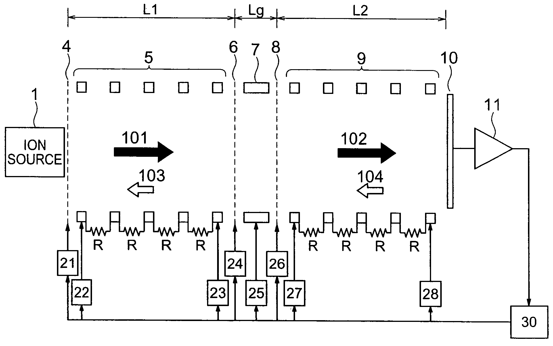
[0027]FIG. 1 is a diagram for illustrating configuration example of an atmospheric-pressure ion-mobility spectrometer according to a first embodiment of the present invention.

[0028]FIG. 2 is a diagram for explaining applied voltages to respective electrodes in respective sequences in the apparatus according to the first embodiment.

[0029]FIG. 3 is a diagram for explaining heat dissociation efficiency (calculation value) in the apparatus according to the first embodiment.

[0030]FIG. 4A and FIG. 4B are conceptual diagrams for explaining effects by the apparatus according to the first embodiment.

[0031]Measurement made by the ion-mobility spectrometer according to the first embodiment includes an ion introduction sequence of introducing first ions generated at an ion source 1 into a first drift region (unit), a first drift sequence of separating the first ions by flight drift times at the first drift region, an ion dissociation sequence (hereinafter, referred to as merely “dissociation se...

second embodiment

[0048]FIG. 5 is a diagram for illustrating configuration example of an atmospheric-pressure ion-mobility spectrometer according to a second embodiment of the present invention.

[0049]FIG. 6A, FIG. 6B, and FIG. 6C are diagrams for explaining configuration of acceleration electrodes in the apparatus according to the second embodiment, and applied voltages to respective electrodes in respective sequences therein. FIG. 6A and FIG. 6B are the diagrams for illustrating the configuration and lay-out of the acceleration electrodes 305a, 305b, 305c, and 305d of array-configured acceleration electrodes 305. FIG. 6C is the diagram for illustrating the applied voltages to the respective electrodes in the respective sequences (i.e., ion introduction sequence, first drift sequence, ion dissociation sequence, and second drift sequence) in the apparatus according to the second embodiment.

[0050]In the second embodiment, the explanation will be given below concerning the configuration of improving the...


PUM


Abstract

There is provided an ion-mobility spectrometer. This apparatus includes the following configuration components: An ion source for generating first ions, a first drift unit for separating the first ions by flight drift times, an ion dissociation unit for generating second ions by dissociating the first ions separated, and a second drift unit for separating the second ions by flight drift times. Moreover, the first drift unit, the ion dissociation unit, and the second drift unit are located inside a chamber whose pressure is set at 10 mTorr or higher. This apparatus allows execution of low-cost and high-resolving-power ion separation and detection.

Description

INCORPORATION BY REFERENCE[0001]The present application claims priority from Japanese application JP 2004-293191 filed on Oct. 6, 2004, the content of which is hereby incorporated by reference into this application.BACKGROUND OF THE INVENTION[0002]1. Field of the Invention[0003]The present invention relates to an ion-mobility spectrometer and an ion-mobility analysis method for analyzing ions ionized at an ion source.[0004]2. Description of the Related Art[0005]Ion mobility spectrometry has been widely used for gas detection such as explosive detection. In addition to ion detection method based on the ion mobility, a mass spectrometry method exists as ion detection method. In the ion mobility spectrometry, ion separation is performed by the ion mobility differences. Meanwhile, in the mass analysis method, the ion separation is performed by mass-to-charge ratios. Namely, these two methods differ fundamentally. In the ion mobility method, the separation is performed under a pressure o...

Claims


Application Information

Patent Timeline
Patent Type & Authority Patents(United States)
IPC IPC(8): H01J49/40B01D59/44
CPCG01N27/622
Inventor HASHIMOTO, YUICHIROHASEGAWA, HIDEKIWAKI, IZUMI
Owner HITACHI LTD
Why Eureka
Try Eureka