Support for hanging objects displayed on a wall

a technology for supporting objects and walls, applied in the direction of machine supports, suspension devices, domestic objects, etc., can solve the problems of less rigid supports and less capable of suitably clipping what, and achieve the effect of strong grip

Inactive Publication Date: 2007-08-28
COTE RENALD
View PDF15 Cites 12 Cited by
  • Summary
  • Abstract
  • Description
  • Claims
  • Application Information

AI Technical Summary

Benefits of technology

[0018]It is a main advantage of this invention to provide for a resiliently deforming support which maintains a strong grip over time and over various width of material to be gripped.

Problems solved by technology

The drawback over most of the prior art is that over time, a certain fatigue makes the support less rigid and less capable of suitably clipping what it is supposed to be holding.

Method used


Image

  • Support for hanging objects displayed on a wall
  • Support for hanging objects displayed on a wall
  • Support for hanging objects displayed on a wall

Examples


Embodiment Construction

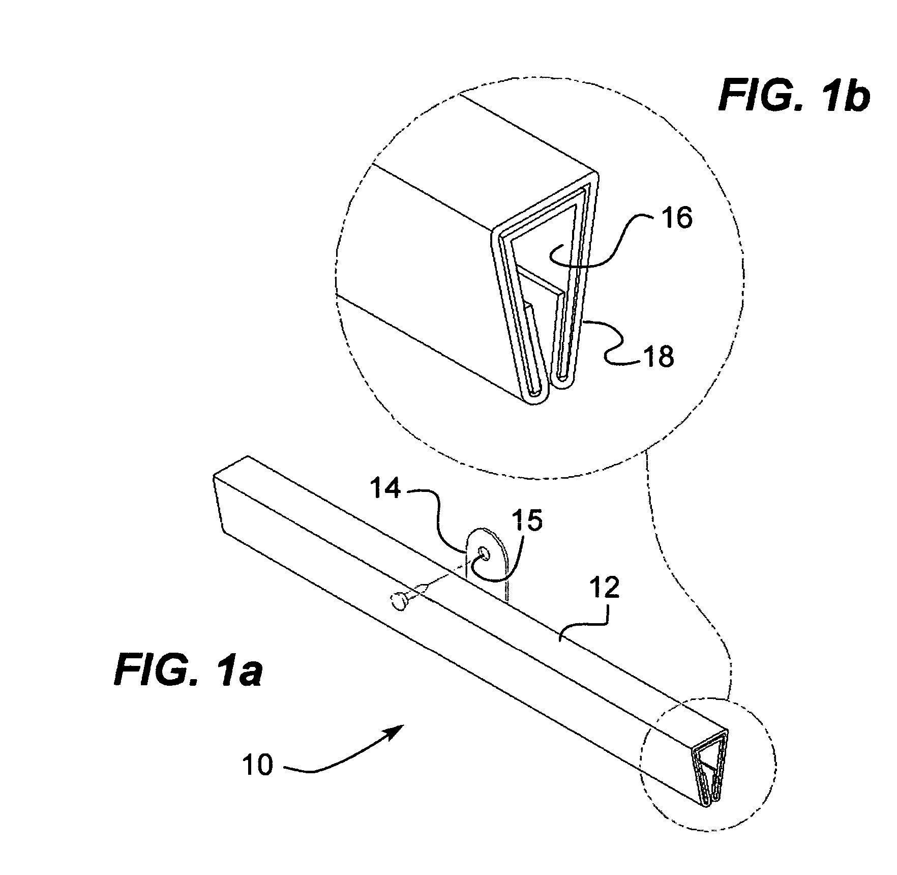
[0025]FIG. 1a Perspective view of the invention.

[0026]FIG. 1b Perspective view detail of FIG. 1a.

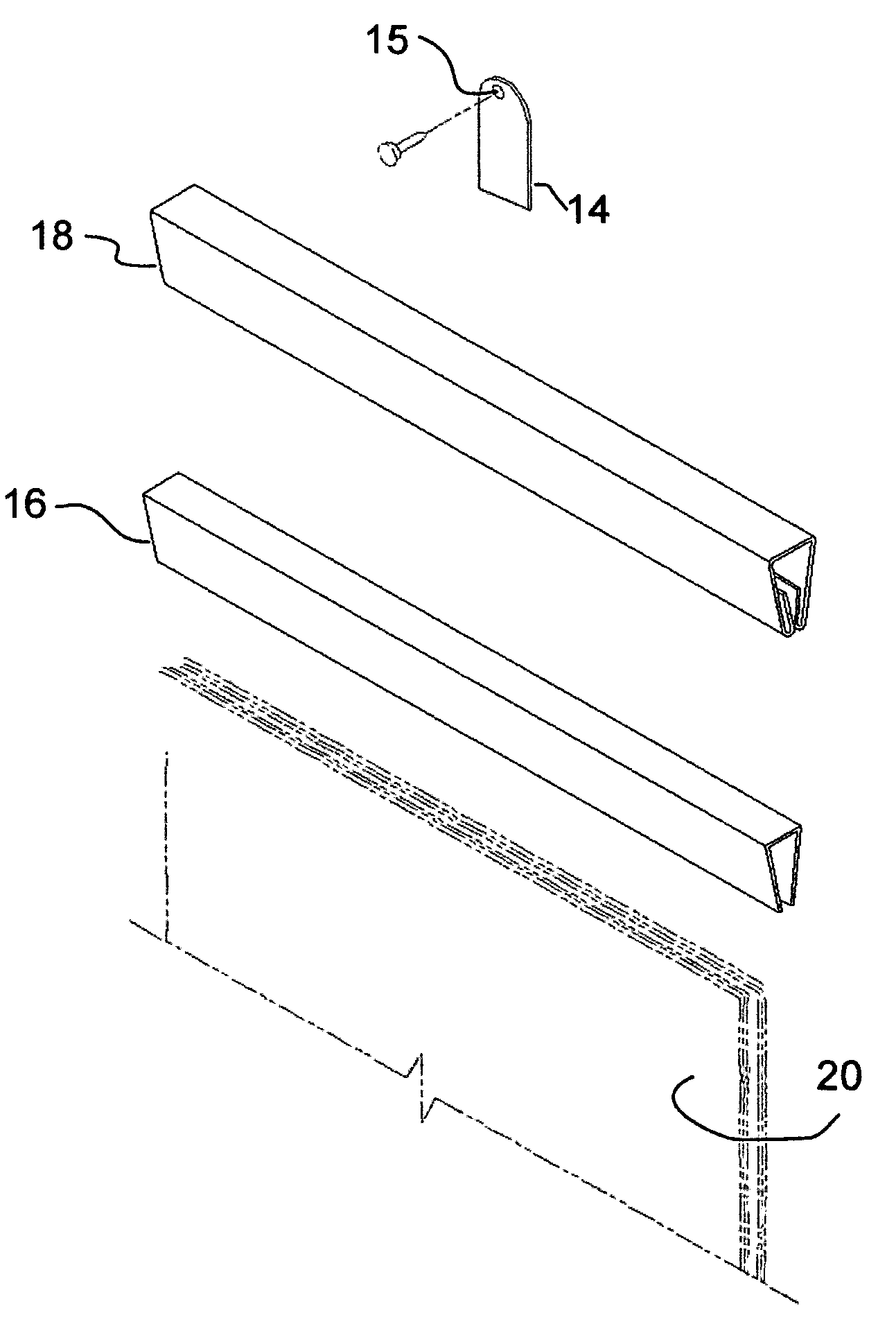
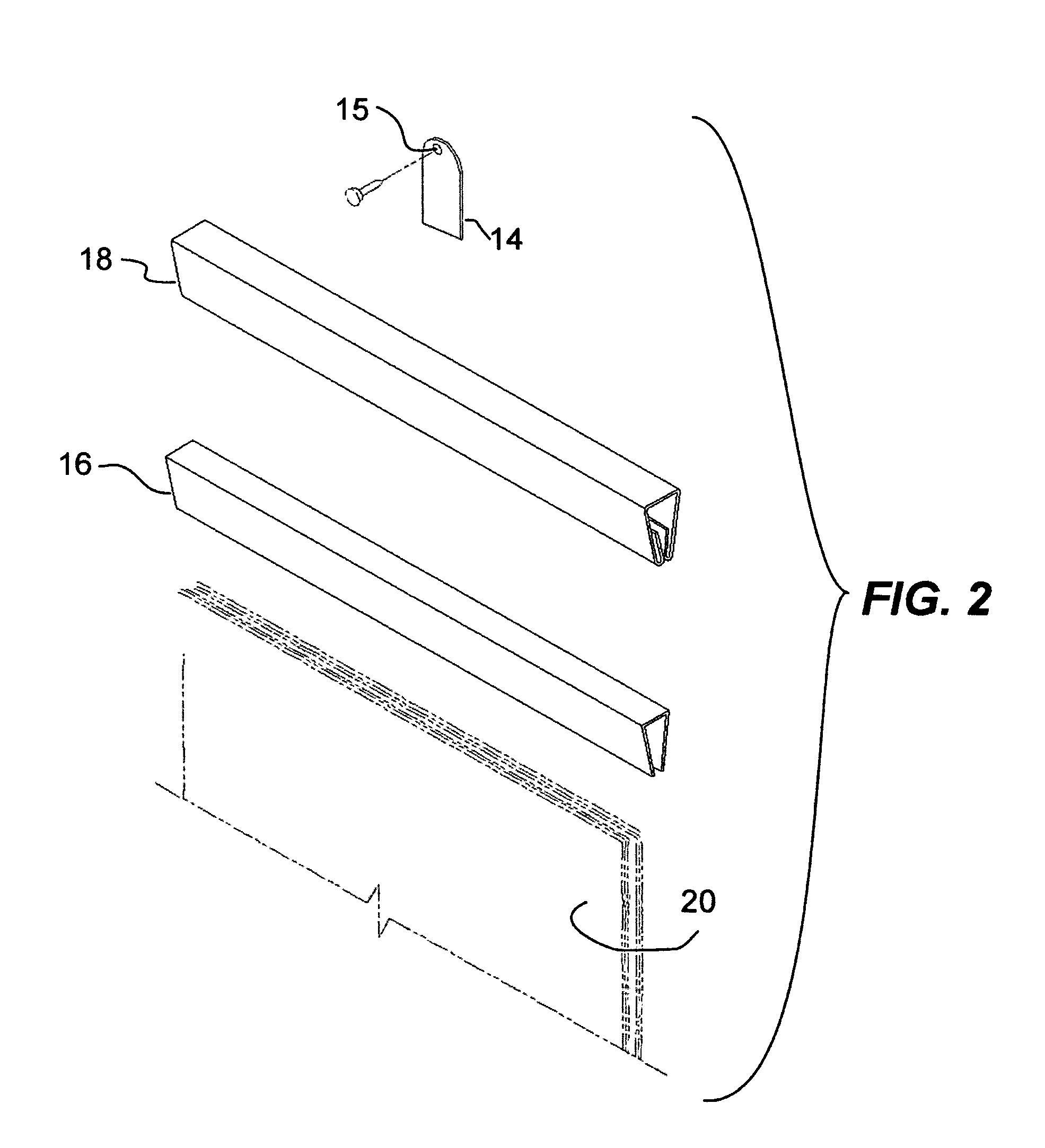
[0027]FIG. 2 Perspective exploded view of the invention.

[0028]FIGS. 3abc Top front and side views respectively of the invention.

[0029]FIGS. 4ab Front and side detail of the hanging tab.

DETAILED DESCRIPTION OF THE PREFERRED EMBODIMENT

[0030]A support for hanging objects (10) is comprised of a support bar (12) The support bar has a hanging tab (14) allowing for hooking on a frame hook (not shown), or such mechnanical equivalents as described hereinabove, by passing through a hole (15). The hanging tab (14) is attached to the support bar by any one of a variety of known attachment means with the preferred being by way of an adhesive. The support bar (12) is subdivided into two distinct parts which are usually found one inside the other that is a > shaped element (16) is frictionally slid and fitted within a holding element (18). The > shaped element (16) provides added resiliency while the ...


PUM


Abstract

A support for hanging objects displayed on a wall consists of a <<U>> shaped element integrated within a holding element. The <<U>> provides the added resiliency while the holding element provides the holding surface to frictionally hold the material to be held. Additionally, a hanging tab attached to the holding element to allow for hooking on a frame hook or, in this context, mechanical equivalents such as a screw, a tack, or a nail.

Description

BACKGROUND OF THE INVENTION[0001]1. Field of the Invention[0002]The invention relates generally to hangers and supports but more particularly to a support for hanging objects on a wall.[0003]2. Background of the Invention[0004]There are several support devices involving a horizontal bar clipping objects such as wall calendars, posters, etc. . . Seen laterally, they can have the shape of an inverted <> and some have the shape of a <<W>>.[0005]U.S. Pat. No. 773,392 shows a <> shaped clip to hold papers within a cover.[0006]U.S. Pat. No. 1,165,108 shows a semi circular clip to hold sheets.[0007]U.S. Pat. No. 3,350,045 shows a <> shaped clip to hold sheets.[0008]U.S. Pat. No. 3,606,507 shows a < shaped clip to hold sheets.[0009]U.S. Pat. No. 3,671,004 shows a holding clip to hold sheets.[0010]U.S. Pat. No. 3,914,892 shows top and bottom <> clips.[0011]U.S. Pat. No. 4,105,127 shows an an outer hollow <> shaped rod and cover.[0012]U.S. Pat. No....

Claims


Application Information

Patent Timeline
Patent Type & Authority Patents(United States)
IPC IPC(8): A47G1/10
CPCA47B97/02A47F5/0006B42F9/008B42F15/06G09F1/10
Inventor COTE, RENALD
Owner COTE RENALD
Why Eureka
Try Eureka