
Compact cantilever rolling mill and a method of producing a metallic product

a cantilever mill and compact technology, applied in the field of cantilever mills for rolling metal products, can solve the problems of inability to handle as high rolling forces of cantilever mills, and large bearings and mill frames. achieve the effect of light bearings and higher rolling forces

Inactive Publication Date: 2007-08-21
LUVATA OY
View PDF5 Cites 2 Cited by
  • Summary
  • Abstract
  • Description
  • Claims
  • Application Information

AI Technical Summary

Benefits of technology

"The invention is a new type of cantilever rolling mill that solves problems of previous designs. It uses lighter bearings and higher rolling forces, making it suitable for applications where heavy bearings were previously necessary. The new design is also faster and cheaper to build and has a gap adjustment mechanism. Overall, the invention expands the usefulness of cantilever rolling mills and makes them more efficient and cost-effective."

Problems solved by technology

This high rolling force and the bending of the shafts are requiring very massive bearings and mill frame for the rolling stand.
However, even in this solution the forces with the support rolls are quite high because the unsuitable angles with the transfer of the rolling forces to the support rolls.
Despite the stronger bearings and other described solutions the cantilever rolling mills are not capable to handle as high rolling forces as “normal” rolling mills.
This limits the use of the cantilever mills seriously despite of the many benefits achieved with this mill construction over “normal” mill construction.

Method used


Image

  • Compact cantilever rolling mill and a method of producing a metallic product
  • Compact cantilever rolling mill and a method of producing a metallic product
  • Compact cantilever rolling mill and a method of producing a metallic product

Examples


Embodiment Construction

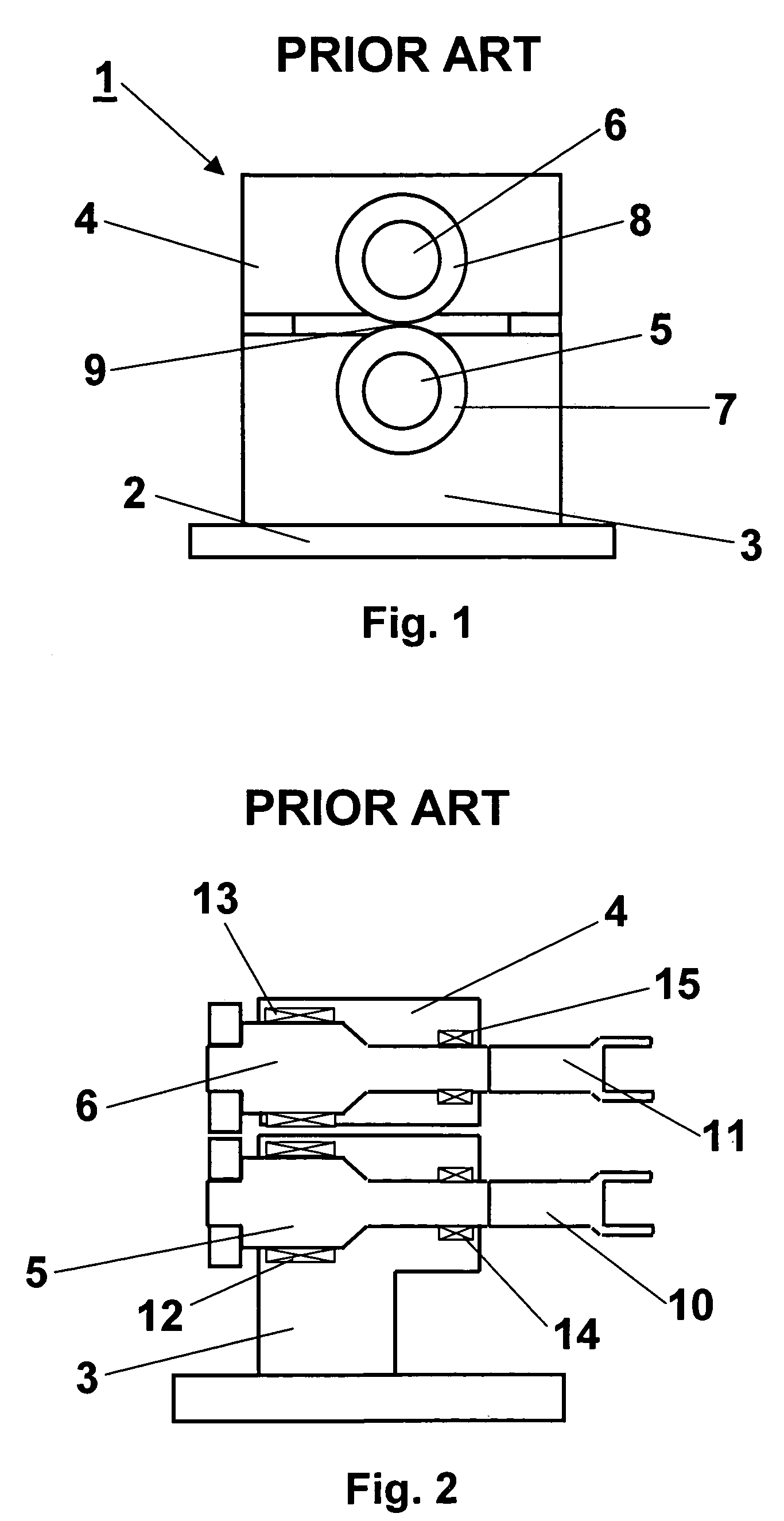
[0021]In FIG. 1 is a simple presentation of a prior art assembly of typical cantilever type rolling mill 1. The rolling mill 1 has a base 2, which is supporting the lower mill frame 3. The lower mill frame 3 is supporting the upper mill frame 4. To the frames 3 and 4 are mounted lower and upper roll shafts 5 and 6. To the shafts 5 and 6 are mounted ring rolls 7 and 8, which are forming a nip 9 in between.

[0022]FIG. 2 is another view of the prior art cantilever mill of FIG. 1. Both roll shafts 5 and 6 have drive ends 10 and 11 correspondingly at the ends of the roll shafts for driving the mill with drive motors. The roll shafts 5 and 6 are mounted to the mill frames 3 and 4 with heavy main bearing assemblies 12 and 13 and lighter bearing assemblies 14 and 15, which are situated closer to the drive ends 10 and 11 of the roll shafts. The heavy main bearing assemblies 12 and 13 are carrying the main part of the rolling forces. The light bearing assemblies 14 and 15 are just balancing th...


PUM

PropertyMeasurementUnit
strengthaaaaaaaaaa
mechanicalaaaaaaaaaa
metallicaaaaaaaaaa

Abstract

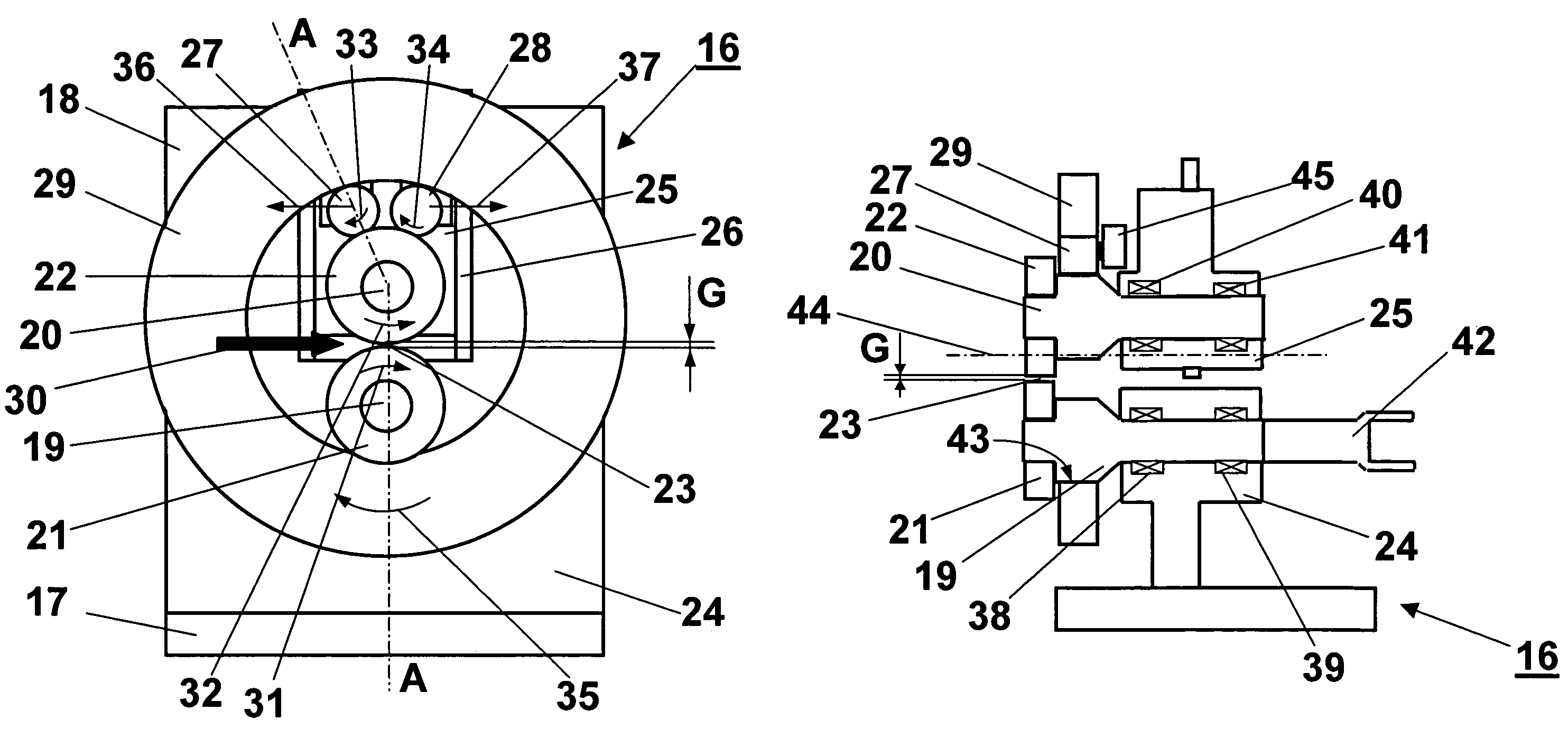
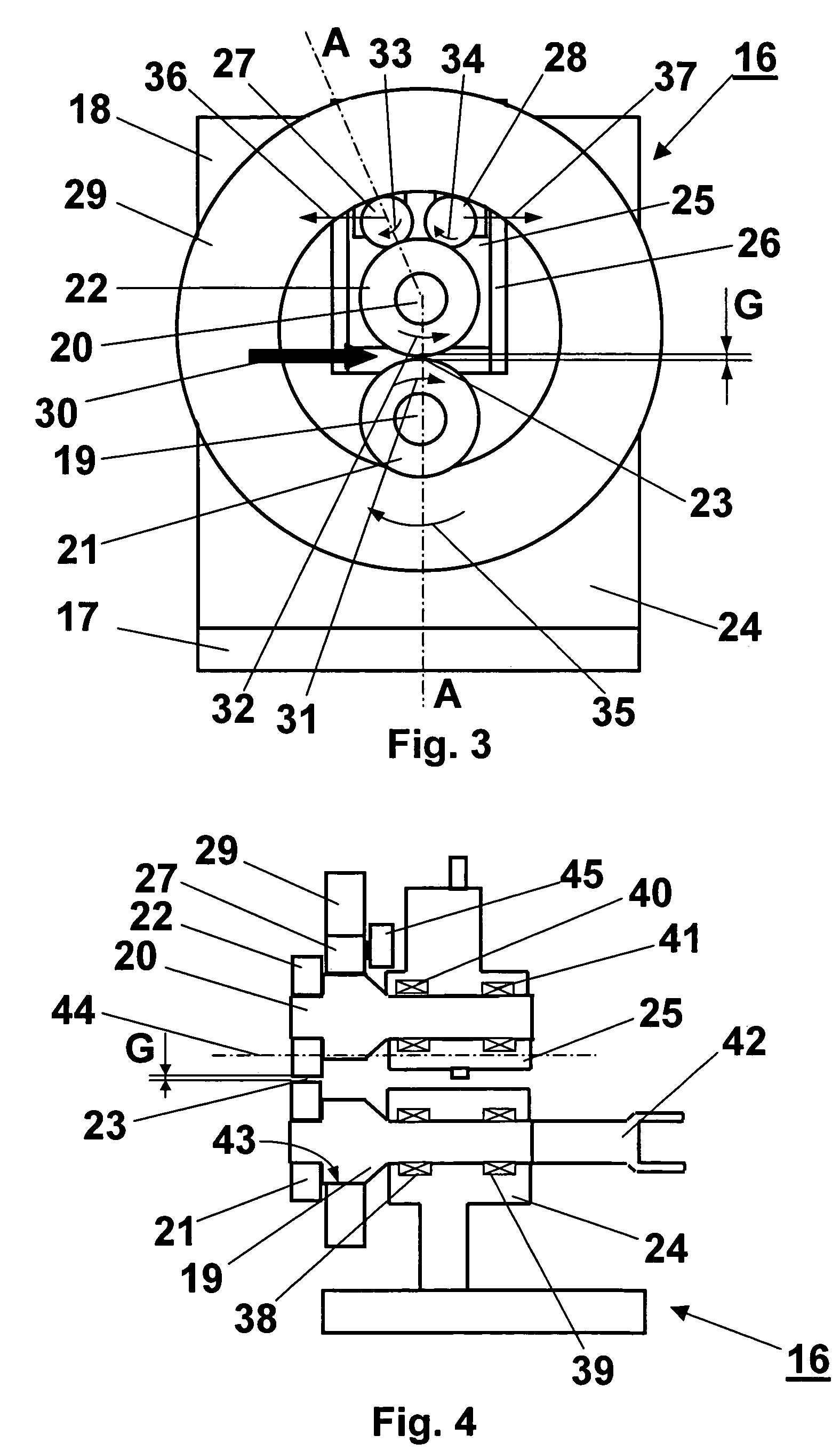
The invention relates to an apparatus for rolling a metallic product comprising a mill frame (18), a first cantilever roll shaft (19), a second cantilever roll shaft (20), both said roll shafts (19, 20) being mounted on the mill frame (18) with two sets of bearing assemblies (38, 39, 40, 41), a first rolling ring (21) mounted on the first roll shaft (19), a second rolling ring (22) mounted on the second roll shaft (20) said rolling rings (21, 22) forming a nip (23) in between, at least one ring (29) arranged with its inside surface (43) in rolling contact with the first roll shaft (19) and with at least one intermediate roll (27), which intermediate roll (27) is arranged also in rolling contact with the second roll shaft (20) and at least one drive end (42) arranged at the end of either roll shafts (19, 20) for driving the mill (16). The invention also relates to a method of producing a metallic product.

Description

BACKGROUND OF THE INVENTION[0001]This invention relates in general to mills for rolling metal products such as strands, strips, wires and profiles. More specifically, it relates to a cantilever apparatus of compact size for rolling a metallic material and a method of producing a metallic product.[0002]Rolling mills are used for reducing the thickness and shaping of metallic products. There are two kinds of rolling mills. First there are rolling mills where work rolls have strong supportive bearings connecting the work rolls to the mill frame at both ends of the work rolls and the mill frame is covering the whole rolling mill. These are called “normal” rolling mills. The other kind of mills are called cantilever rolling mills, where the actual rolling is done outside the mill frame and the work rings are assembled on roll shafts which are supported by the mill frame only from the other side of the nip. The term “nip” is used herein to refer to the region where the work rolls or rolli...

Claims


Application Information

Patent Timeline
Patent Type & Authority Patents(United States)
IPC IPC(8): B21B29/00B21B13/14B21B39/20B21B13/00B21B31/02B21B31/16
CPCB21B13/005B21B29/00B21B31/02B21B31/16
Inventor KOPPINEN, ILPOSWANK, BRIANKEIFE, HANS
Owner LUVATA OY
Learn More