
Emergency lighting system and method

a lighting system and emergency lighting technology, applied in the field of emergency lighting systems, can solve the problems of system not including emergency detection capability or power supply source, design that might not lend itself to cost-effective retrofitting, and become obscured

Active Publication Date: 2007-08-14
EMERGENT LIGHTING
View PDF11 Cites 33 Cited by
  • Summary
  • Abstract
  • Description
  • Claims
  • Application Information

AI Technical Summary

Benefits of technology

Enables safe evacuation in emergency situations by providing clear, smoke-penetrable lighting and directional cues without requiring complex circuitry or software, while being cost-effective and easily retrofittable to existing structures.

Problems solved by technology

These signs, however, are generally located near the ceiling, and may become obscured by the presence of smoke in a smoke / fire emergency.
Also, these signs generally provide no indication as to whether or not the escape path through the exit is actually safe for use as an escape path.
This system did not, however, include emergency detection capability or a power supply source.
Additionally, this system was designed to be installed in the floor, either embedded in the floor covering or installed at the junction of the floor and the walls, a design that might not lend itself to cost-effective retrofitting.
This prior art provides all of the information that a person needs to exit a building safely in case of fire, but its applicability to the general populace is likely limited by its sophistication and its price.
This prior art also does not provide simple emergency lighting in a power outage, that can be provided at a low cost.

Method used


Image

  • Emergency lighting system and method
  • Emergency lighting system and method
  • Emergency lighting system and method

Examples


Embodiment Construction

[0015]The present invention and its advantages are best understood by referring to the drawings. The elements of the drawings are not necessarily to scale, emphasis instead being placed upon clearly illustrating the principles of the invention. Throughout the drawings, like numerals are used for like and corresponding parts of the various drawings.

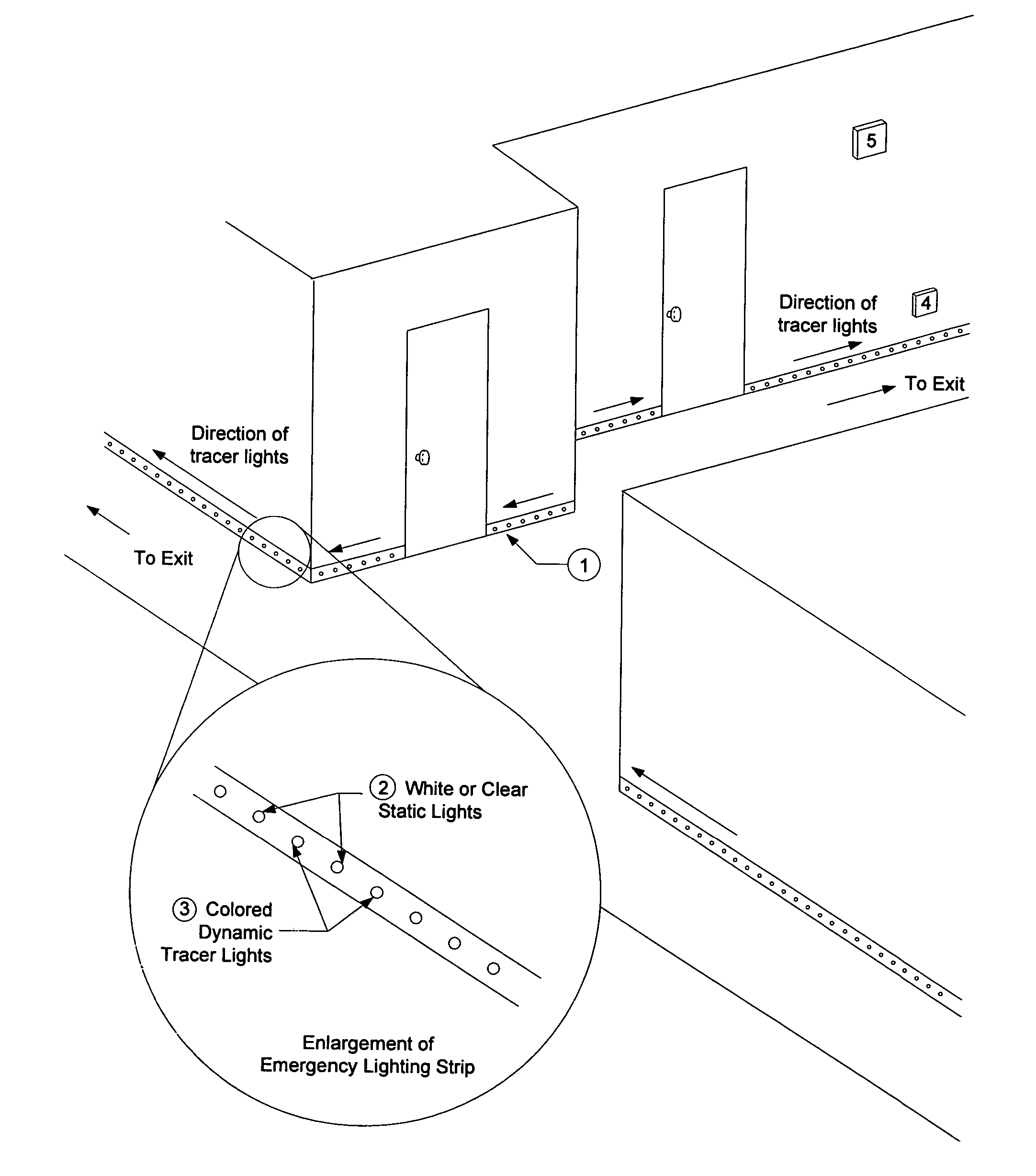
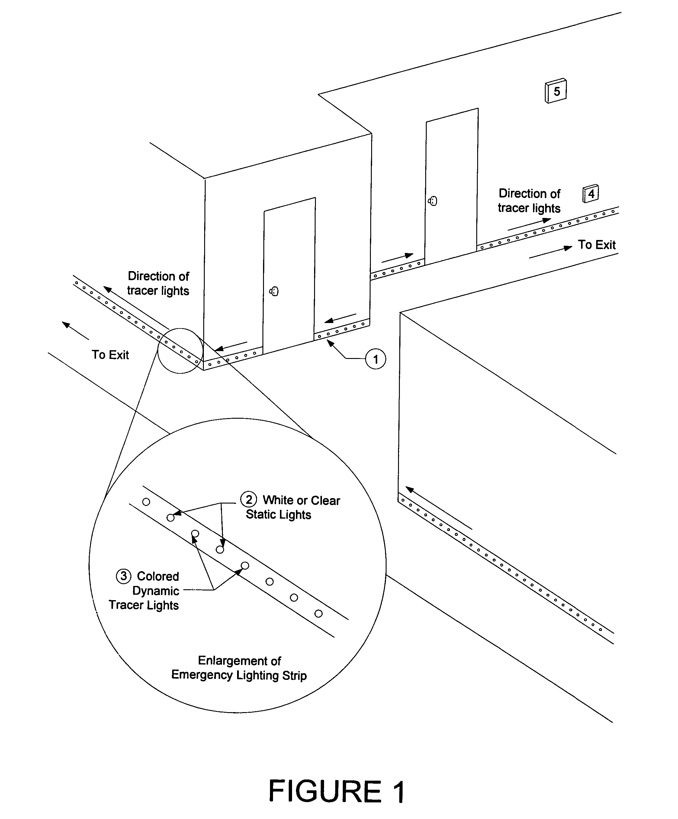
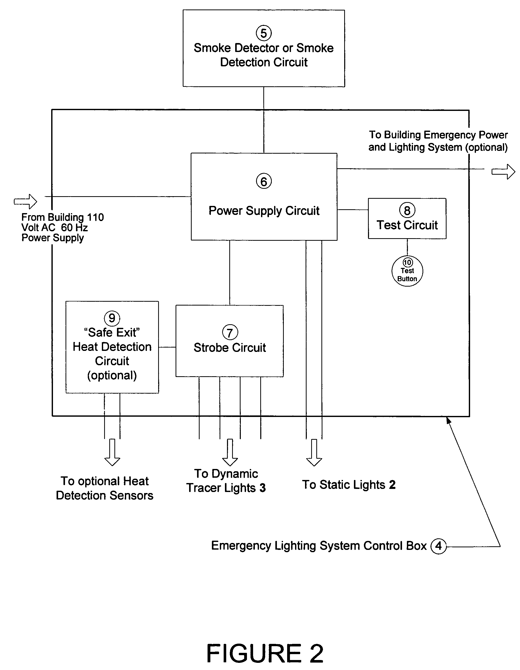
[0016]FIG. 1 illustrates one embodiment of the emergency lighting system installed the hallways of a building. In this embodiment, emergency lighting strips 1 are stalled into baseboard located near the floor of the building's hallways and contain white or clear static lights 2 (e.g., white or clear light emitting diodes, or LEDs) alternating with colored dynamic “tracer lights”3 (e.g., colored LEDs), which flash intermittently with intense light that can penetrate dense smoke. The emergency lighting strips can be manufactured into molding / baseboard materials that contain the emergency lights or retrofitted into existing materials. In one ...


PUM


Abstract

An improved system and method for providing emergency lighting and directional exit indication in the event of power outage and / or smoke / fire events. The system provides a lighted pathway consisting of discrete points of light, some of which strobe or trace toward the exits and others of which burn steadily for general area emergency lighting. The method consists of detecting the emergency condition and illuminating the appropriate emergency lighting.

Description

BACKGROUND[0001]1. Field[0002]The present invention relates generally to the field of emergency lighting systems. More particularly, the present invention consists of an emergency lighting system and method for lighting and indicating escape paths in emergencies and / or for providing emergency lighting in a power outage situation.[0003]2. Background of the Invention[0004]A safe escape route from a home or building is critical in emergencies such as fire / smoke emergencies and power outages. In order to exit safely, a person must be aware of the safe escape route and must also be able to see well enough to maneuver through the escape route. In commercial buildings, traditional “EXIT” signs are used to point the way to safety in emergency situations. These signs, however, are generally located near the ceiling, and may become obscured by the presence of smoke in a smoke / fire emergency. Also, these signs generally provide no indication as to whether or not the escape path through the exi...

Claims


Application Information

Patent Timeline
Patent Type & Authority Patents(United States)
IPC IPC(8): F21S8/00F21S10/00F21S4/00F21V21/00G08B5/36G08B7/06
CPCF21S4/006F21S8/032G08B7/066F21Y2101/02F21S9/022F21S4/24F21Y2115/10
Inventor PETERSON, JOHN W.
Owner EMERGENT LIGHTING
Learn More