Display stand

a display stand and stand technology, applied in the field of display stands, can solve the problems of insufficient compelling force, difficult to maintain the angle of the display stand, etc., and achieve the effects of convenient operation, sufficient positioning capability, and fast angle adjustmen

Active Publication Date: 2007-07-31
TCL CHINA STAR OPTOELECTRONICS TECH CO LTD
View PDF17 Cites 24 Cited by
  • Summary
  • Abstract
  • Description
  • Claims
  • Application Information

AI Technical Summary

Benefits of technology

[0007]One object of the present invention is to provide an angle adjustable display stand, using a pull rod at a fixed position to control a sliding locking bar to move along a single direction to be separated from a rack so as to practice a fast and convenient operation.
[0010]For attaining the objects mentioned above, a connecting seat and one end of a supporting plate are pivotally connected to a base in an angle adjustable display stand according to the present invention. And then, a vertical slot is disposed on the connecting seat and is operated in coordination with a slider installed movably on the supporting plate. A rack and a control section are respectively disposed on the two flank sides of the vertical slot. A locking bar disposed in the control section is accepted in the slider and one end thereof is engaged with the rack. A pull rod of the control section is pulled to move a skewed slot so as to drive the locking bar to move along a single direction to be separated from the rack after the panel and the connecting seat are combined together. And then, the slider is made to slide up and down along a slide slot so as to change a relative angle between the connecting seat and the supporting plate. Finally, a positioning is completed after the pulling rod is released. Whereby, the present invention can provide a display stand with convenient operation and fast angle adjustment. Besides, a rack and locking bar are locked to each other to position a display stand so as to provide a display stand enough positioning capability.

Problems solved by technology

However, the angle of the panel 11 is not easy to be maintained, because the pivoting shaft 131 is worn away after using for a long time, resulting the insufficient compelling force.

Method used


Image

  • Display stand
  • Display stand
  • Display stand

Examples


Embodiment Construction

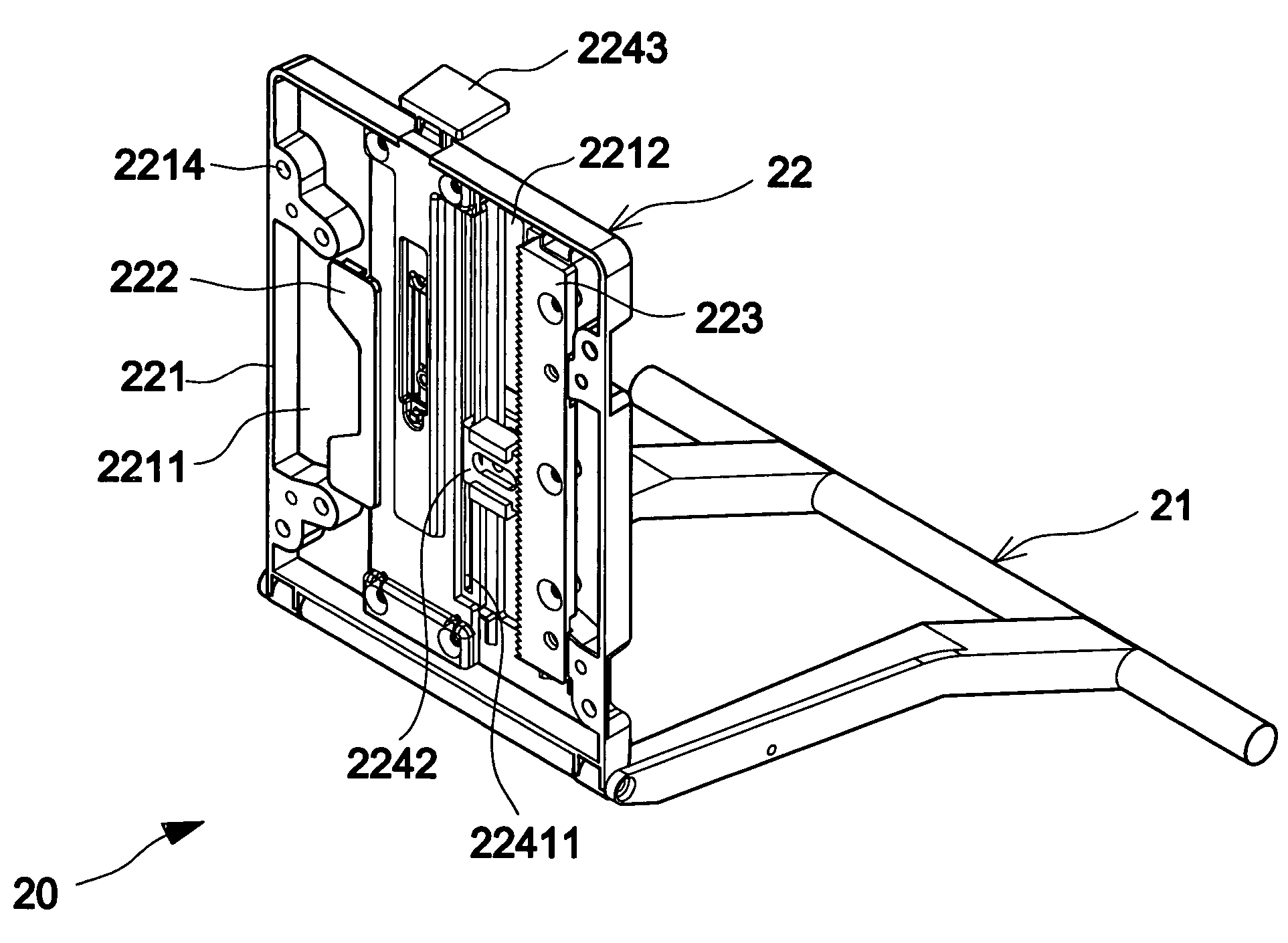
[0019]Please refer to FIGS. 2 and 3. An angle adjustable display stand 20 comprises a base 21, connecting seat 22 and supporting plate 23, in which two level legs 211 are extended respectively to two flank sides at the rear end of the base 21; one end of the connecting seat 22 is pivotally connected to the front end of the base 21. The connecting seat 22 comprises a seat body 221 and a covering plate 222 installed at the top of the seat body 221. An accepting groove 2211 whose rim is disposed with raised connecting holes 2214 is for connecting with every kind of panel. A vertical slide slot 2212 whose two flank sides are respectively installed with a rack 223 and a control section 224 that are operated in coordination with each other is opened at the bottom of the accepting groove 2211. A plurality of engaging teeth is disposed at one side of the rack 223 facing the slide slot 2212.

[0020]The control section 224 comprises a sliding plate 2241, a locking bar 2242 and a pull rod 2243. ...


PUM


Abstract

A display stand comprises a connecting seat and supporting plate. A vertical guiding slot is disposed on said connecting seat. A rack and a control section are installed respectively at the two flank sides of the vertical guiding slot, in which the control section has a locking bar accepted in the slider, and one end thereof is engaged with the rack. After a panel is combined with connecting seat, said locking bar is driven to move along a single direction to be separated from the engagement of said rack by pulling the pull rod of the control section to push a skewed slot, and the slider is caused to slide up and down along the sliding slot by pulling said pull rod so as to change a relative angle between the connecting seat and the supporting plate. Finally, the pull rod is released to complete a positioning.

Description

BACKGROUND OF THE INVENTION[0001]1. Field of the Invention[0002]The present invention relates to a display stand, and more particularly to an angle adjustable display stand.[0003]2. Description of Related Art[0004]LCD (Liquid Crystal Device) is broadly used as a computer screen or television. With the technology development, LCD having originally a display function is developed to a device having touch control and handwriting functions. This allows an user to select a function directly on a display or input by handwriting.[0005]Please refer to FIG. 1A and FIG. 1B. A display panel 11 is installed on a connecting seat 12 of a conventional LCD 10, and then a pivoting shaft 131 engaged with several round washers 132 is used to lock the panel 11 through nuts 133 so as to allow the two ends of the connecting seat 12 to connect pivotally with a supporting plate 13. The rebounding force yielded from the washers 133 allows compelling the supporting plate 13 and the connecting seat 12 tightly...

Claims


Application Information

Patent Timeline
Patent Type & Authority Patents(United States)
IPC IPC(8): A47F5/12F16M11/10G06F1/16H04N5/64G09F9/00
CPCF16M11/10F16M2200/024F16M11/2057G06F1/1601
Inventor CHUEH, CHIEN-TSAIYUAN, MIN HAO
Owner TCL CHINA STAR OPTOELECTRONICS TECH CO LTD
Why Eureka
Try Eureka