
Pulley fixing apparatus of image forming apparatus

a technology of image forming apparatus and fixing apparatus, which is applied in the direction of belt/chain/gearing, printing, and printing, etc., can solve the problems of increasing manufacturing cost, achieve easy mounting and dismount, and easily control the tension of the power-transmitting belt, and simplify the structure

Inactive Publication Date: 2007-07-24
S PRINTING SOLUTION CO LTD
View PDF8 Cites 7 Cited by
  • Summary
  • Abstract
  • Description
  • Claims
  • Application Information

AI Technical Summary

Benefits of technology

"The present invention provides an improved pulley fixing apparatus for an image forming apparatus that can easily mount and dismount a power-transmitting belt and a driven pulley, and easily control the tension of the power-transmitting belt. The apparatus has a simplified structure and assembly process, reducing manufacturing costs and assembly time. It includes a pulley fixing part rotatably fixing the driving pulley and the driven pulley, a sliding part movably supporting the pulley fixing part, an automatic tension adjusting part elastically urging the power-transmitting belt, and a locking part to lock the pulley fixing part after adjusting the tension of the belt. The apparatus can easily adjust the tension of the belt and is easy to assemble and disassemble."

Problems solved by technology

Also, since the conventional pulley fixing apparatus 70 uses a large number of parts, manufacturing cost is increased.

Method used


Image

  • Pulley fixing apparatus of image forming apparatus
  • Pulley fixing apparatus of image forming apparatus
  • Pulley fixing apparatus of image forming apparatus

Examples


Embodiment Construction

[0042]Reference will now be made in detail to the embodiments of the present invention, examples of which are illustrated in the accompanying drawings, wherein like reference numerals refer to the like elements throughout. The embodiments are described below to explain the present invention by referring to the figures.

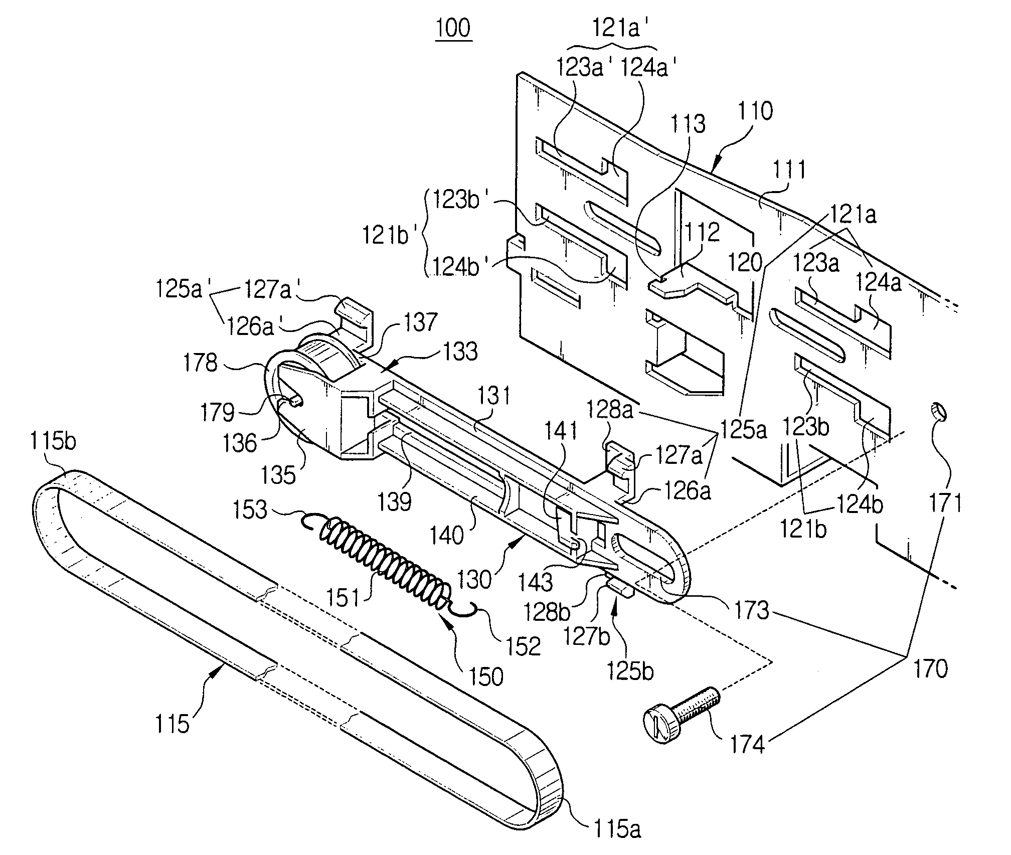
[0043]Referring now to FIG. 5, there is illustrated a pulley fixing apparatus 100 of an image forming apparatus, to fix a driven pulley to engage with one side of a power-transmitting belt, in accordance with an embodiment of the present invention.

[0044]The image forming apparatus, for example an inkjet printer, to which the pulley fixing apparatus 100 of the present invention is applied, has a carrier transfer belt 115 transmitting a driving force to a power-transmitting saw tooth (not shown) formed at a carrier (not shown) mounting a print head (not shown) having a nozzle for jetting ink, a carrier driving motor (not shown) having a driving pulley (not shown) dispose...


PUM


Abstract

A pulley fixing apparatus of an office machine having a pulley fixing part rotatably fixing a driven pulley on a frame, a sliding part movably supporting the pulley fixing part on the frame, and an automatic tension adjusting part elastically urging the pulley fixing part in a direction such that the driven pulley imparts a predetermined tension to a power-transmitting belt. The pulley fixing apparatus readily enables mounting and dismounting of the power-transmitting belt and the driven pulley and control of the power-transmitting belt tension by simplifying structure and assembly. Further, the pulley fixing apparatus reduces manufacturing cost and assembly time by decreasing the number of parts.

Description

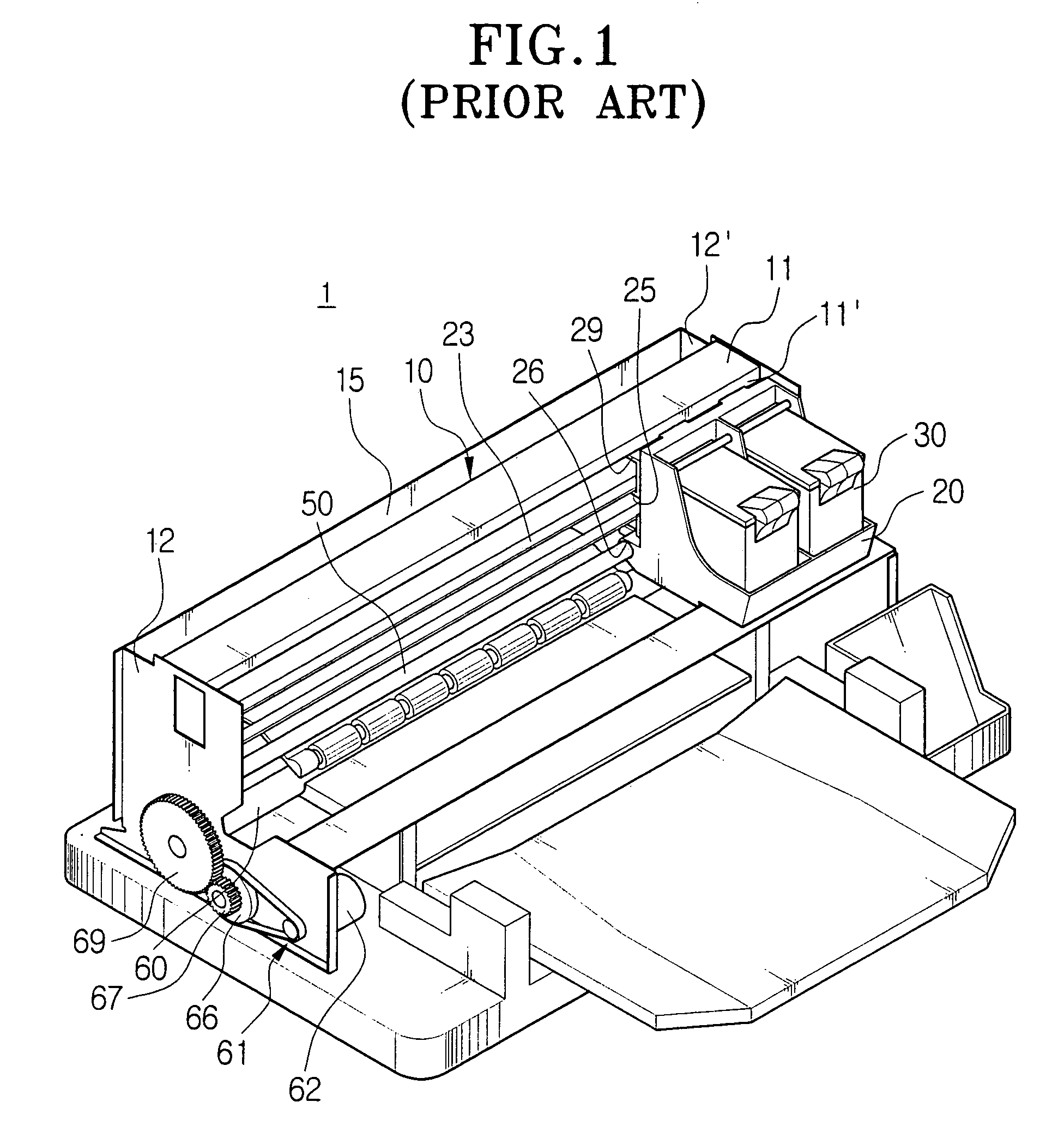
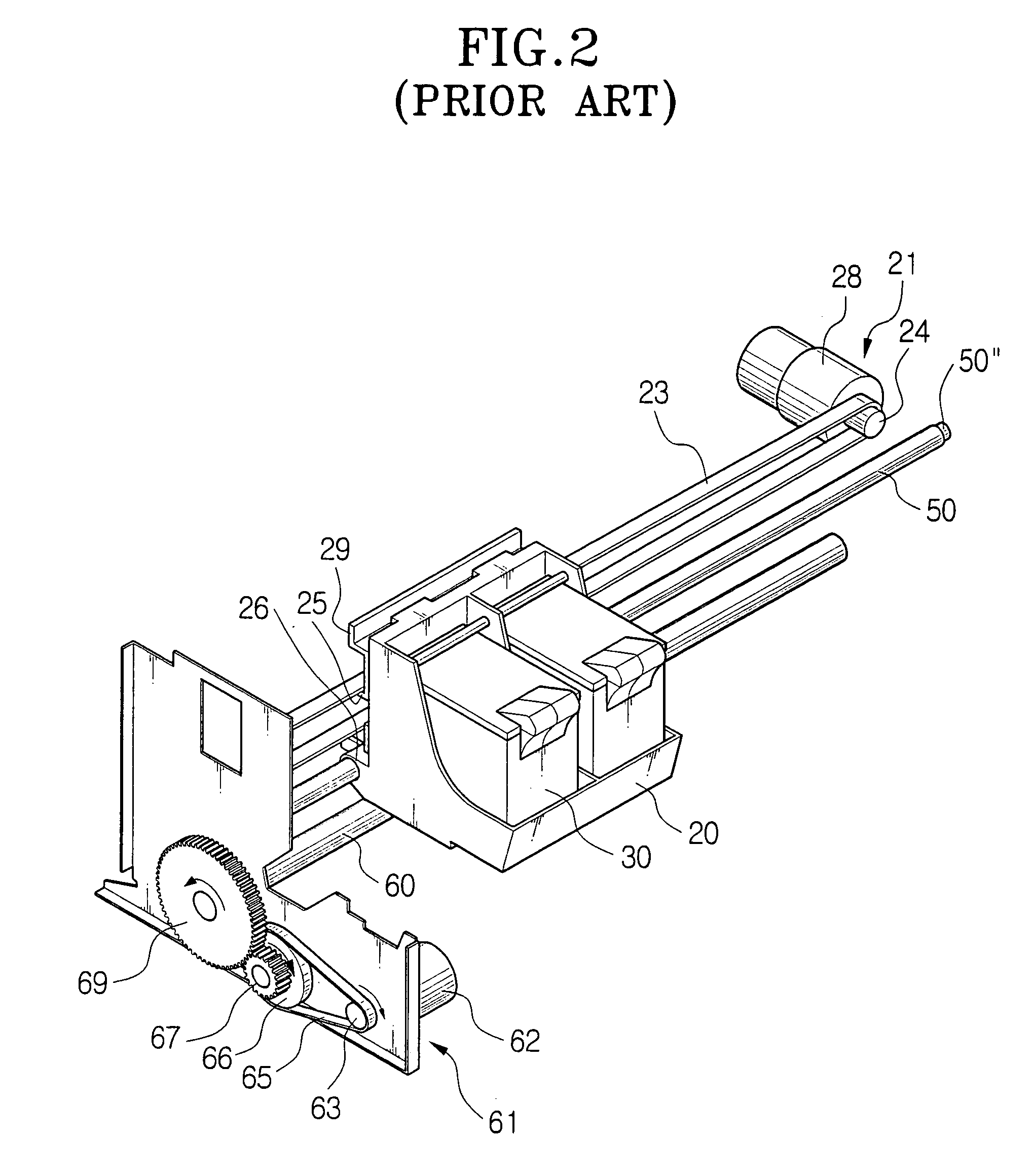
CROSS-REFERENCE TO RELATED APPLICATIONS[0001]This application claims the benefit of Korean Application No. 2002-68490, filed Nov. 6, 2002, in the Korean Intellectual Property Office, the disclosure of which is incorporated herein by reference.BACKGROUND OF THE INVENTION[0002]1. Field of the Invention[0003]The present invention relates to an image forming apparatus, and may be an inkjet printer, a facsimile machine, a laser printer, etc., and more particularly, to a pulley fixing apparatus of an image forming apparatus, which can easily mount and dismount a power-transmitting belt and a driven pulley, and easily control a tension of the power-transmitting belt.[0004]2. Description of the Related Art[0005]Generally, an image forming apparatus, for example an inkjet printer 1, has a carrier 20 mounting a print head 30 having a nozzle for jetting ink, a chassis 10 having side frames 12 and 12′ to support a guide rail 11 and a carrier shaft 50 guiding the movement of the carrier 20, a ca...

Claims


Application Information

Patent Timeline
Patent Type & Authority Patents(United States)
IPC IPC(8): F16H7/08B41J23/02B41J19/00F16H7/12
CPCB41J19/005F16H7/1263F16H2007/0808B41J23/02
Inventor YOUN, KARP-SIK
Owner S PRINTING SOLUTION CO LTD
Learn More