Communication system
- Summary
- Abstract
- Description
- Claims
- Application Information
AI Technical Summary
Benefits of technology
Problems solved by technology
Method used
Image


Examples
first embodiment
[0034]the present invention will hereinafter be described with reference to FIGS. 1 through 7.
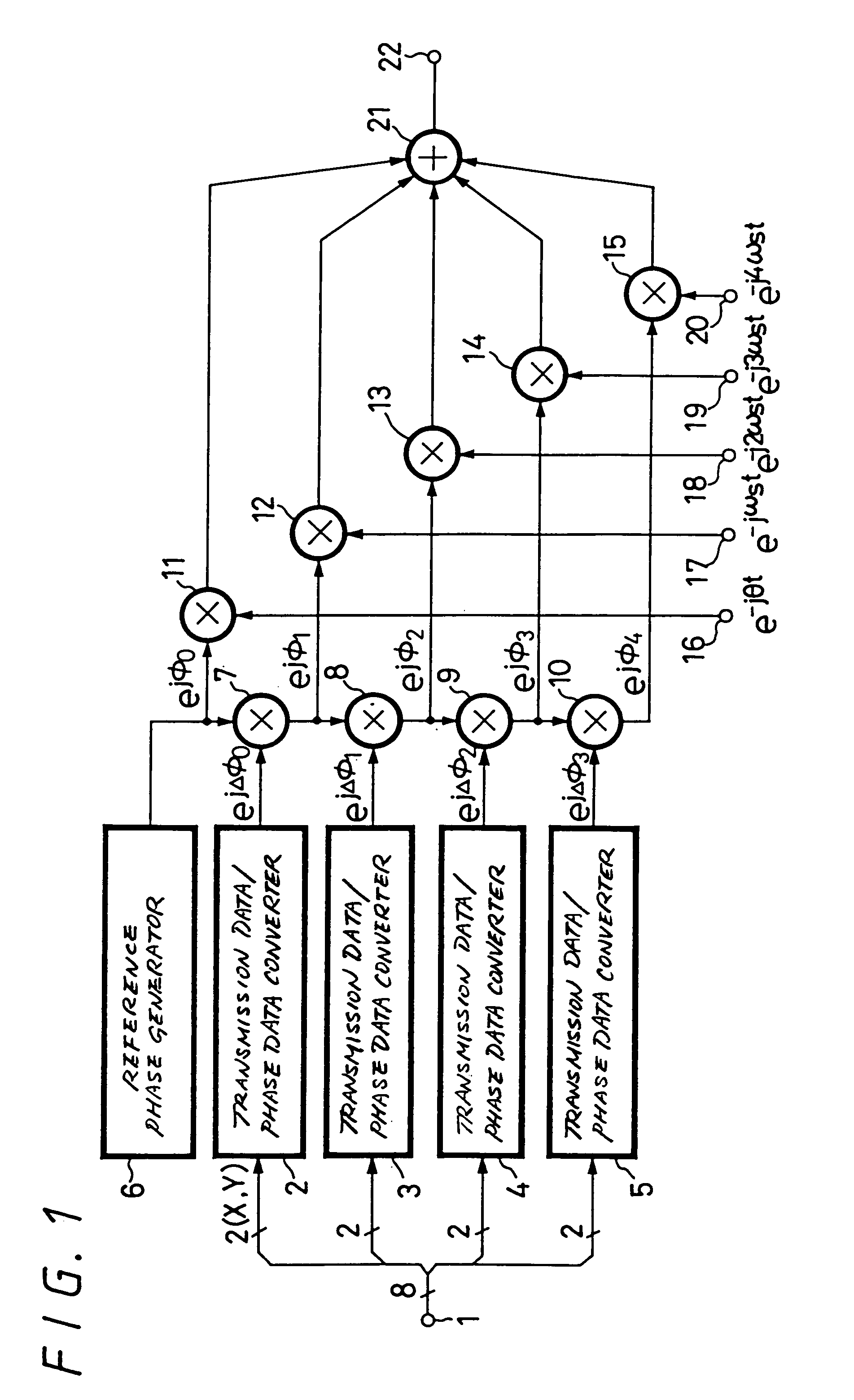
[0035]In this embodiment, the present invention is applied to a communication system wherein digital data is transmitted via radio waves. Digital data is transmitted by a transmission processing system shown in FIG. 1.
[0036]As shown in FIG. 1, 8-bit data is sequentially supplied to a transmission data input terminal 1 and 8-bit data is processed as one modulation unit by the circuit according to this embodiment. The 8-bit data is divided into 2-bit data each. The 2-bit data thus divided are supplied to transmission data / phase data converters 2, 3, 4, 5. The transmission data / phase data converters 2 through 5 generate phase data based on the states of 2-bit data [X, Y] supplied thereto. As the states of the 2-bit data [X, Y], there are considered four states expressed on the following table 1. The transmission data / phase data converters 2 through 5 generate different phase data Δφ at every f...
second embodiment
[0090]A communication system according to the present invention will be described with reference to FIGS. 8 and 9. In FIGS. 8 and 9, like parts corresponding to those of FIGS. 1 to 7 are marked with the same references and therefore need not be described in detail.
[0091]According to this embodiment, similar to the example shown in FIG. 1, the present invention is applied to a communication system wherein digital data is transmitted and received via radio waves. FIG. 8 shows an arrangement of a transmission system. The transmission processing circuit shown in FIG. 8 is the same in arrangement as that of the transmission processing circuit shown in FIG. 1 where the outputs of the carrier multipliers 11 to 15 are mixed by the mixer 21. Then, the output of the mixer 21 is supplied to a multiplier 24 for multiplying a time waveform. A time waveform output from a time waveform generator 23 is multiplied with a transmission signal at every modulation unit by the multiplier 23 and a multipl...
third embodiment
[0095]A communication system according to the present invention will be described with reference to FIG. 10. In FIG. 10, like parts corresponding to those of FIGS. 1 to 9 are marked with the same references and therefore need not be described in detail.
[0096]According to this embodiment, similar to the example shown in FIG. 1, the present invention is applied to a communication system wherein digital data is transmitted and received via radio waves. The transmission processing circuit shown in FIG. 10 is arranged as a circuit for multiplying a transmission signal with a time waveform similar to the transmission processing circuit shown in FIG. 8. In this embodiment, carrier signals having different frequencies obtained at the first, second, third, fourth and fifth carrier input terminals 16, 17, 18, 19 and 20 are supplied to multipliers 16a, 17a, 18a, 19a and 20a, in which they are multiplied with time waveforms of every modulation unit output from the time waveform generator 23. Th...
PUM
 Abstract
Description
Claims
Application Information
 - R&D
- Intellectual Property
- Life Sciences
- Materials
- Tech Scout
- Unparalleled Data Quality
- Higher Quality Content
- 60% Fewer Hallucinations
Browse by: Latest US Patents, China's latest patents, Technical Efficacy Thesaurus, Application Domain, Technology Topic, Popular Technical Reports.
© 2025 PatSnap. All rights reserved.Legal|Privacy policy|Modern Slavery Act Transparency Statement|Sitemap|About US| Contact US: help@patsnap.com