
Paddle handle latch release device and spring latch system using same

a technology of latch release device and paddle handle, which is applied in the direction of carpet fasteners, keyhole guards, mechanical controls, etc., can solve the problems of many complex construction, high production cost, and early failure of common us

Inactive Publication Date: 2007-07-03
WESCO DISTRIBUTION
View PDF12 Cites 46 Cited by
  • Summary
  • Abstract
  • Description
  • Claims
  • Application Information

AI Technical Summary

Problems solved by technology

Many are too complicated in construction or expensive to produce for common usage, or are prone to early failure.

Method used


Image

  • Paddle handle latch release device and spring latch system using same
  • Paddle handle latch release device and spring latch system using same
  • Paddle handle latch release device and spring latch system using same

Examples


Embodiment Construction

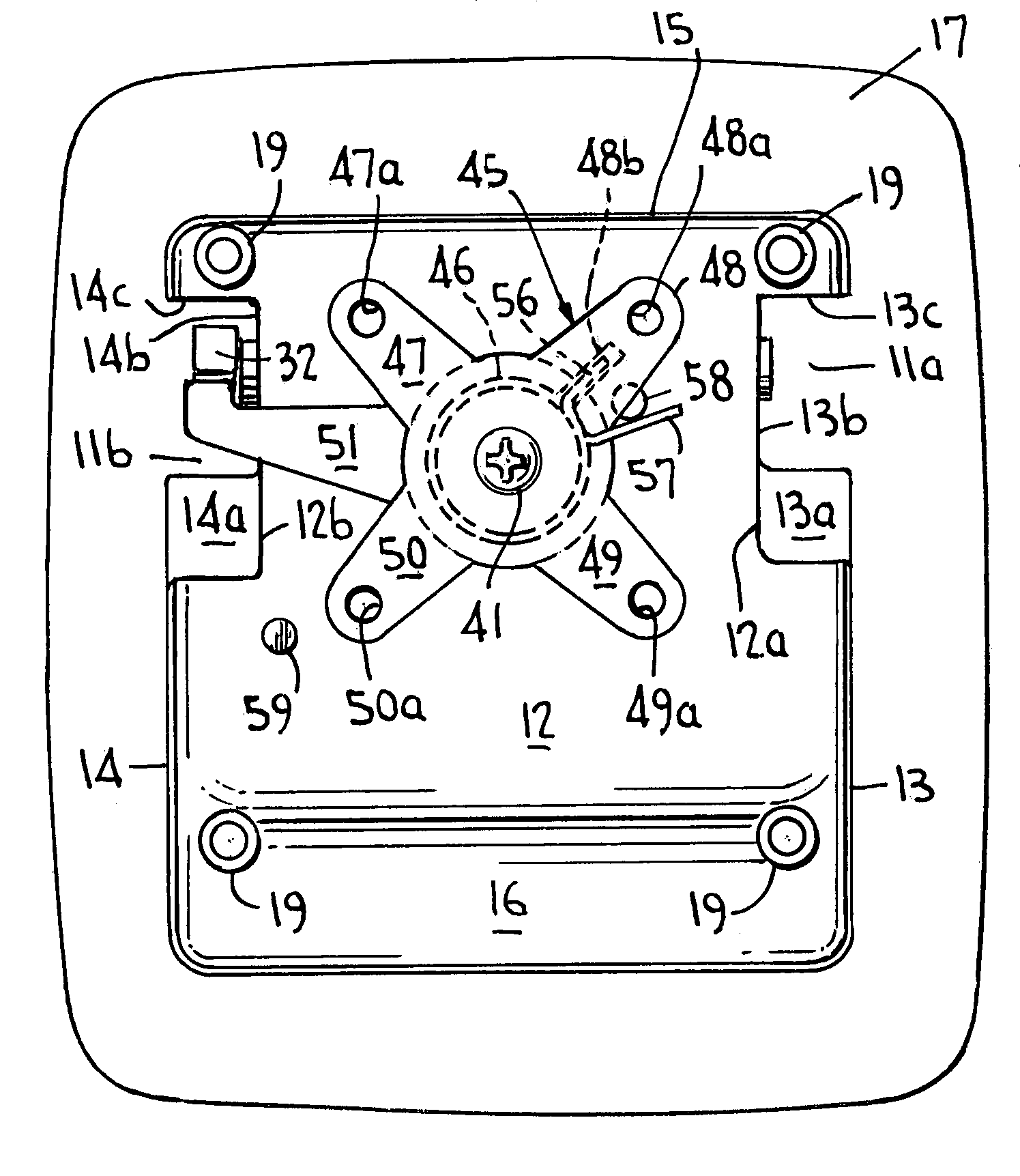
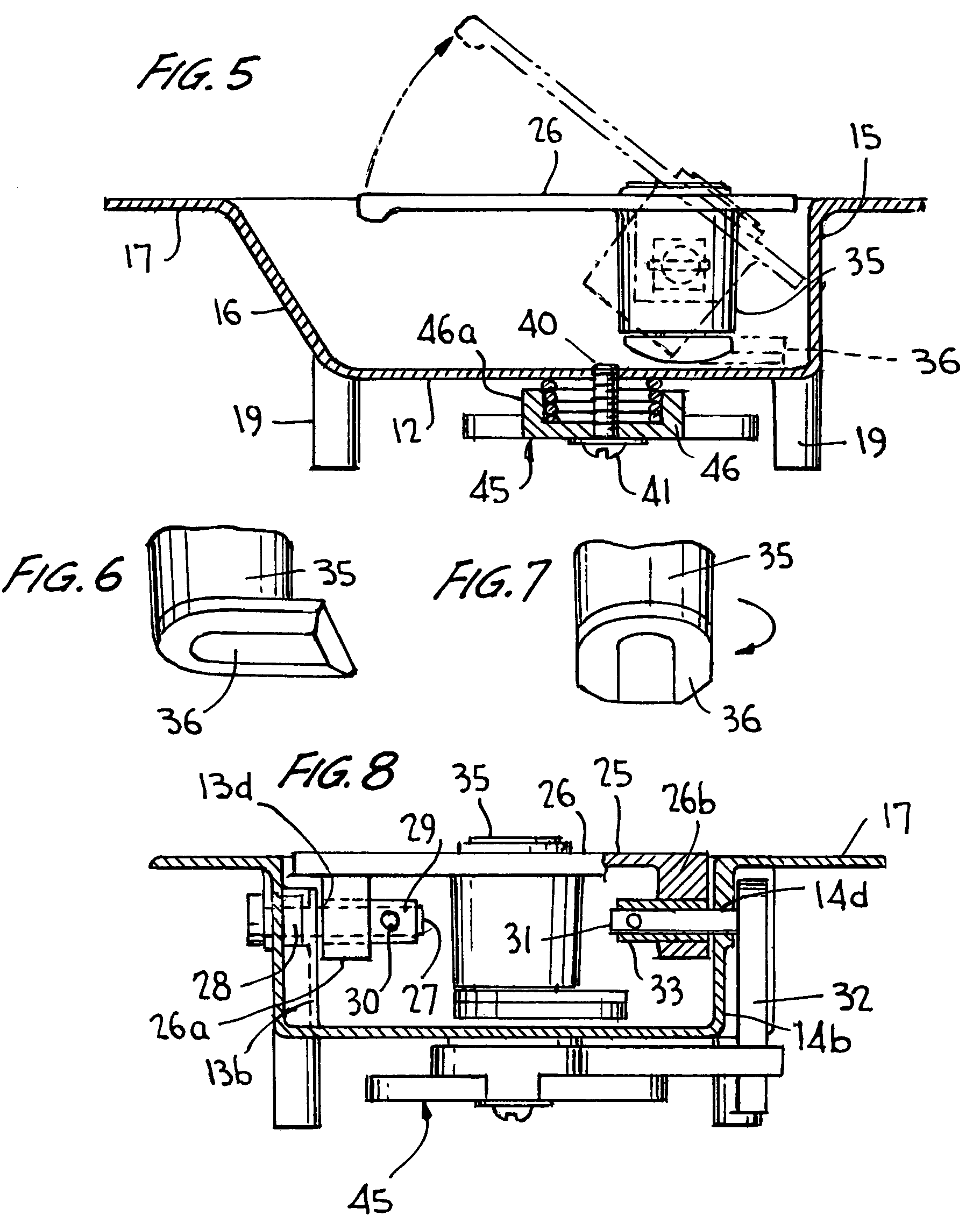
[0016]A paddle handle latch release device according to a preferred embodiment of the present invention is generally labeled 10 in FIG. 1. It includes a pan housing 11 and a paddle handle member 25 which is mounted in the pan housing. A key-operated cylinder lock 35 is mounted in the paddle handle member.

[0017]As best seen in FIGS. 2, 3, 5 and 8, the pan housing 11 includes a floor 12, a left side wall 13, a right side wall 14, an upper end wall 15, a lower end wall 16 and a rim 17. The floor 12 is generally rectangular except for generally rectangular cut-out areas 12a and 12b on opposite sides thereof near the upper end wall 15. The left side wall 13 includes side segments 13a, 13b, and 13c which extend from the floor 12 to the rim 17, and the right side wall 14 includes side segments 14a, 14b and 14c which extend from floor 12 to the rim 17. It can be seen from FIGS. 2 and 3 that side segments 13a and 14a are sloped between the floor 12 and the rim 17, as is the lower end wall 16...


PUM


Abstract

A paddle handle latch release device of a spring latch system includes a paddle handle member pivotally mounted in a pan housing, the paddle handle member including an actuating lever which extends below a floor of the pan housing; a spider member rotatably mounted to the underside of the floor, the spider member including latch arms extending from a hub and an operating arm in contact with the actuating lever; and a torsion spring which biases the operating arm against the actuating lever; the spider being rotated from an inactive positioning by the actuating lever when the paddle handle member is manually rotated from a lowered positioning to a lifted positioning, and the torsion spring returning the spider member to an inactive positioning and the paddle handle member back to a lowered positioning when the paddle handle member is released.

Description

BACKGROUND OF THE INVENTION[0001]1. Field of the Invention[0002]The present invention relates to spring latch systems which include one or more spring latches to releasably connect one member to another member, such as a door to or within a door frame, and to latch release devices used in such systems.[0003]2. The Prior Art[0004]Spring latch systems for releasably connecting two members together, such as a door or other types of closure member to or within a frame member, are very well known. Such systems include one or more spring latches and a release device for unlocking (opening) the spring latches when it is desired to separate the connected members. Various types of spring latches and various types of release devices have been devised. Many are too complicated in construction or expensive to produce for common usage, or are prone to early failure.SUMMARY OF THE INVENTION[0005]According to my invention, a spring latch system includes at least one spring latch and a paddle handl...

Claims


Application Information

Patent Timeline
Patent Type & Authority Patents(United States)
IPC IPC(8): E05C1/06
CPCE05B5/00E05B13/10E05C9/06E05C9/16E05C9/00E05B53/003Y10S292/31Y10T292/0844Y10T292/57
Inventor TWEEDY, TIMOTHY
Owner WESCO DISTRIBUTION
Learn More