
Image forming apparatus and method for adjusting image forming apparatus

a technology of image forming apparatus and forming apparatus, which is applied in the direction of electrographic process apparatus, printing, instruments, etc., can solve the problems of color misregistration, disturbance of the output of the detector, and increase the cost of the apparatus, so as to reduce the cost, shorten the time required, and accurately adjust the position

Active Publication Date: 2007-06-26
SHARP KK
View PDF9 Cites 5 Cited by
  • Summary
  • Abstract
  • Description
  • Claims
  • Application Information

AI Technical Summary

Benefits of technology

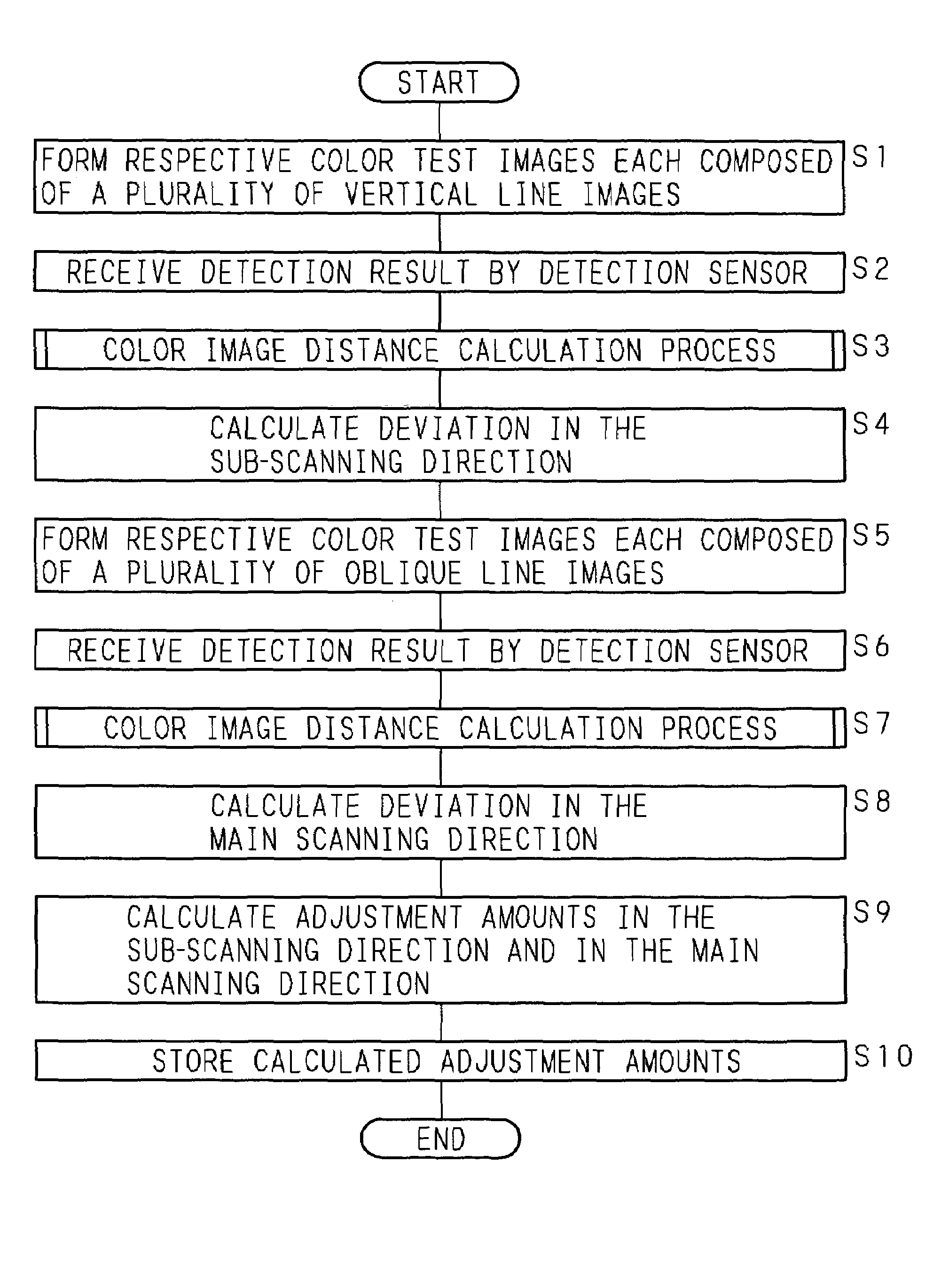
The present invention provides an image forming apparatus and method for adjusting it that can accurately adjust the positions of color images without narrowing the region where the color images can be adjusted. This is achieved by using a test image formed on the medium, and detecting and calculating the distance between the test image and the color images formed on the medium. The method includes the steps of forming a color test image composed of a plurality of partial images, calculating the partial image distance between the test image and the color images, and calculating the color image distance between the test image and the color images. The apparatus includes a plurality of image forming means, irradiating means, and detecting means. The technical effects of the invention include reducing the time and cost required for color registration adjustment and achieving a reduction in the size of the apparatus.

Problems solved by technology

Therefore, the positions on the transfer medium where the respective color images are formed easily deviate from each other, and consequently such an image forming apparatus has a serious problem that the image quality may be lowered by color misregistration.
In order to accurately detect the deviation between the positions of the respective color images, it is necessary to use a high-resolution detector, and consequently, the cost of the apparatus increases.
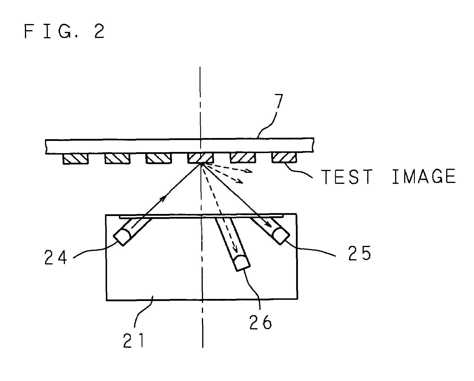
However, with a low-resolution detector, among reflection light to be incided on a light receiving unit in the light irradiated from the light emitting unit of the detector, the area of part of light reflected on the image is large, and consequently irregular reflection light also incides the light receiving unit in addition to regular reflection light, and a disturbance occurs in the output of the detector.
The disturbance in the output of the detector caused by the irregular reflection light varies depending on various conditions such as the difference in the detection ability of the detector, the mount error of the detector, a temperature change in the image forming apparatus, and changes in the respective components with time, and thus it is difficult to deal with this problem and it is difficult to accurately detect the positional deviation of the respective color images.
Thus, since it is necessary to form test images for color registration adjustment and detect the density for all regions capable of adjusting the positions of the respective color images, there is the problem that the time required for the color registration adjustment becomes longer.
Moreover, a large amount of developer is used for the color registration adjustment, and the running cost increases.
Further, if the time required for the color registration adjustment is shortened, or if the cost, more specifically the amount of developer necessary for the color registration adjustment is reduced, there arises the problem that the region capable of adjusting the positions of the respective color images becomes narrower.

Method used


Image

  • Image forming apparatus and method for adjusting image forming apparatus
  • Image forming apparatus and method for adjusting image forming apparatus
  • Image forming apparatus and method for adjusting image forming apparatus

Examples


Embodiment Construction

[0044]The following description will specifically explain the present invention, based on the drawings illustrating an embodiment thereof.

[0045]FIG. 1 is a schematic vertical sectional view showing an example of the internal structure of an image forming apparatus of the present invention. The image forming apparatus shown in FIG. 1 employs a direct transfer system in which an image is directly transferred to recording paper as a recording medium. The image forming apparatus is constructed to form a multi-color image by using toners of respective colors, namely, black (K), cyan (C), magenta (M) and yellow (Y). The image forming apparatus comprises exposure units 11a, 11b, 11c, 11d; developing devices 12a, 12b, 12c, 12d; photoconductor drums 13a, 13b, 13c, 13d; cleaner units 14a, 14b, 14c, 14d; and charging devices 15a, 15b, 15c, 15d. The alphabets “a”, “b”, “c” and “d” added to the respective numbers correspond to the respective colors, namely, K, C, M, and Y, respectively. One set ...


PUM


Abstract

A color test image of each color composed of a plurality of partial images arranged at predetermined intervals in the moving direction of a conveyance belt is formed, at a position on the conveyance belt separated from relative positions where the respective color images are formed by distances according to the respective colors. A detection sensor detects the position of each partial image, and the distance between corresponding partial images in the respective colors is calculated. The distance between the respective color test images by finding an average value of a plurality of partial image distances is calculated, and based on the calculated distance, an adjustment amount for adjusting a position of forming each color image on the medium is calculated so that the respective color images are superimposed on each other without causing color misregistration.

Description

CROSS-REFERENCE TO RELATED APPLICATION[0001]This non-provisional application claims priority under 35 U.S.C. §119(a) on Patent Application No. 2004-210828 filed in Japan on Jul. 16, 2004, the entire contents of which are hereby incorporated by reference.BACKGROUND OF THE INVENTION[0002]1. Field of the Invention[0003]The present invention relates to an image forming apparatus and a method for adjusting an image forming apparatus, for forming a multi-color image by superimposing color images of respective colors and performing a color registration adjustment to correct color misregistration of the multi-color image.[0004]2. Description of Related Art[0005]In an image forming apparatus for forming a multi-color image, after decomposing inputted data into respective color components, namely black (K), cyan (C), magenta (M) and yellow (Y), and performing image processing, image data of the respective color components are created, and a multi-color image is formed by superimposing color i...

Claims


Application Information

Patent Timeline
Patent Type & Authority Patents(United States)
IPC IPC(8): G03G15/00
CPCG03G15/0194G03G2215/0119G03G2215/0161
Inventor MATSUYAMA, KENGO
Owner SHARP KK
Learn More