
Instrument enclosure apparatus

a technology for enclosure apparatus and instruments, which is applied in the direction of instruments, casings/cabinets/drawers, casings/cabinets/drawers, etc., can solve the problems that the cooling regime designed for the earlier hardware configuration may not be suitable for the new hardware configuration, and the design of the known clamshell instrument enclosure apparatus is therefore not well suited for reus

Inactive Publication Date: 2007-06-26
AGILENT TECH INC
View PDF15 Cites 35 Cited by
  • Summary
  • Abstract
  • Description
  • Claims
  • Application Information

AI Technical Summary

Benefits of technology

The modular design allows for easy reconfiguration of hardware and cooling systems, reducing production costs and enabling the enclosure to accommodate different hardware configurations and cooling needs throughout its lifetime, enhancing flexibility and reuse.

Problems solved by technology

The above manufacturing approach is disadvantageous because such suites of hard tools are expensive and changing the width or length of the instrument enclosure apparatus normally requires a new suite of expensive tools to be designed and used to create the new instrument enclosure apparatus.
Furthermore, should a new configuration of hardware be inserted within the instrument enclosure apparatus, the cooling regime designed for the earlier hardware configuration may not be suitable for the new hardware configuration.
Following manufacture, the above described instrument enclosure apparatus is not flexible in design due to the fixed configuration of the enclosure parts, and therefore, in order to accommodate a new cooling regime, a new instrument enclosure apparatus is typically manufactured.
The disadvantage of present injection moulded clamshell enclosure apparatus is that each particular clamshell instrument enclosure apparatus is designed for a single product and is designed to support a particular cooling regime dependent upon the layout and / or type of hardware it is to accommodate when assembled.
Known clamshell instrument enclosure apparatus designs are therefore not well suited for reuse or to accommodate a change in the layout and / or type of hardware they comprise during their lifetime.

Method used


Image

  • Instrument enclosure apparatus
  • Instrument enclosure apparatus
  • Instrument enclosure apparatus

Examples


Embodiment Construction

[0033]Throughout the following description, identical reference numerals will be used to identify like parts.

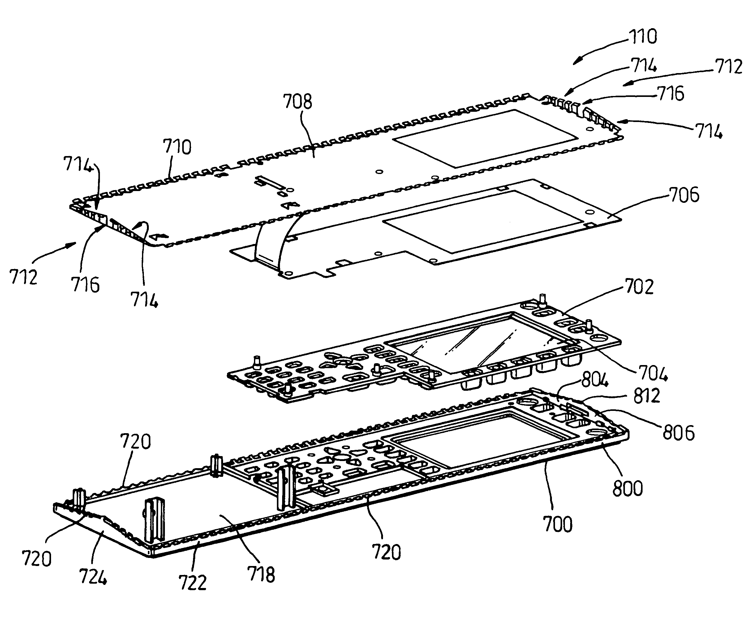
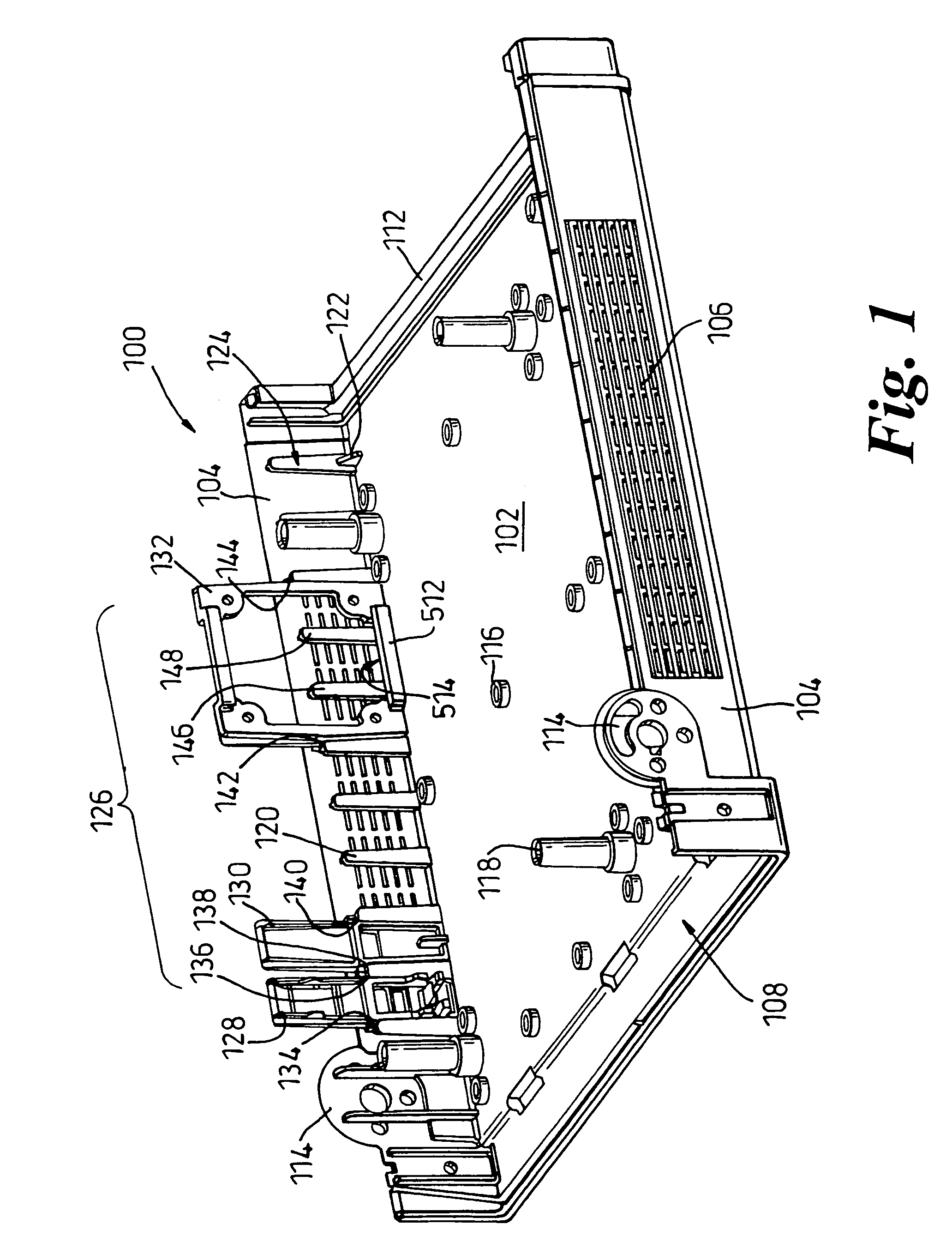
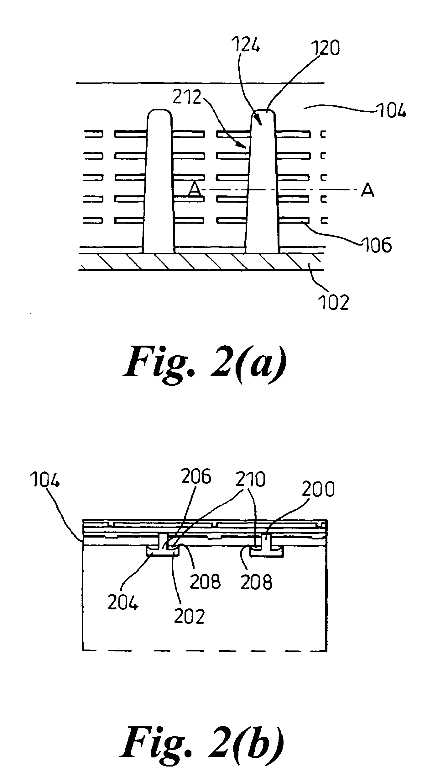
[0034]Referring to FIG. 1, an injection-moulded base portion 100 of a clamshell instrument enclosure apparatus (clamshell) comprises a base 102 and a pair of sidewalls 104 extending substantially perpendicular from the base 102, each sidewall 104 having a plurality of vents 106 disposed therealong. The base portion 100 comprises a front portion 108 for accommodating a display assembly 110 (described in more detail in FIGS. 7 to 11) and a rear portion 112 for accommodating, for example, data signal and power connections between electronic hardware devices arranged within the clamshell (not shown in FIG. 1) and those external to the clamshell. The base portion 100 also comprises a handle connector attachment arrangement 114 for coupling a handle (not shown), for example a bail handle, thereto. When connected, the handle can assume a first position for carrying of the clamshell,...


PUM


Abstract

An instrument enclosure apparatus has a housing with a sidewall and a pair of retaining posts disposed within the housing and adjacent the sidewall, the retaining posts in combination with the sidewall defining a pair of opposing channels for slidably receiving a complementarily shaped insert part. Vents may be disposed along the sidewall of the housing, and the insert part assists in providing adaptable air flow management design.

Description

[0001]This application is a divisional of U.S. application Ser. No. 10 / 641,782, filed 15 Aug. 2003, now U.S. Pat. No. 7,057,884 which is incorporated by reference herein in its entirety.[0002]The present invention relates, in general, to an instrument enclosure apparatus of a type used for enclosing electronic devices such as computer hardware. In particular, the present invention relates to a clamshell instrument enclosure apparatus.BACKGROUND ART[0003]An instrument enclosure apparatus typically comprises a number of computer hardware devices such as a motherboard, Printed Circuit Board (PCB), transformer, fan, display panel and processor. The instrument enclosure apparatus protects the hardware from damage that may arise from shock, vibration or external abrasion and provides a convenient package enabling the hardware to be portable and suitable for bench-top use or rack mounting. The instrument enclosure apparatus may also comprise means to shield the hardware from electromagneti...

Claims


Application Information

Patent Timeline
Patent Type & Authority Patents(United States)
IPC IPC(8): H05K7/20H05K5/02G06F1/18G06F1/20H05K7/14
CPCG06F1/181G06F1/183G06F1/20H05K7/1411H05K7/1461
Inventor DAVIDSON, RONALDRAVIE, DAVID
Owner AGILENT TECH INC
Learn More