
Internal red dot sight

a red dot sight and internal technology, applied in the field of sight, can solve the problems of high cost, still has drawbacks, user may not be able to identify the red dot on the target, etc., and achieve the effect of improving the projection precision of the light source, shortening the device length, and maximizing the size of the objective lens

Inactive Publication Date: 2007-06-26
CHENG LI DER +1
View PDF5 Cites 50 Cited by
  • Summary
  • Abstract
  • Description
  • Claims
  • Application Information

AI Technical Summary

Benefits of technology

The design achieves a shorter device length, increased objective lens size, reduced manufacturing costs, and improved projection precision while ensuring safe and undistorted red dot visibility, even in high ambient light conditions.

Problems solved by technology

Further, when the intensity of the ambient light is high, the user may be unable to identify the red dot on the target.
This design is functional, however it still has drawbacks.
Further, this design uses a big number of lenses, resulting in a high cost.
If the internal red dot sight falls to the ground accidentally, the angle of reflection of the laser beam will be biased, resulting in a focusing failure.
In this case, the laser beam may injure the user's eye.

Method used


Image

  • Internal red dot sight
  • Internal red dot sight
  • Internal red dot sight

Examples


Embodiment Construction

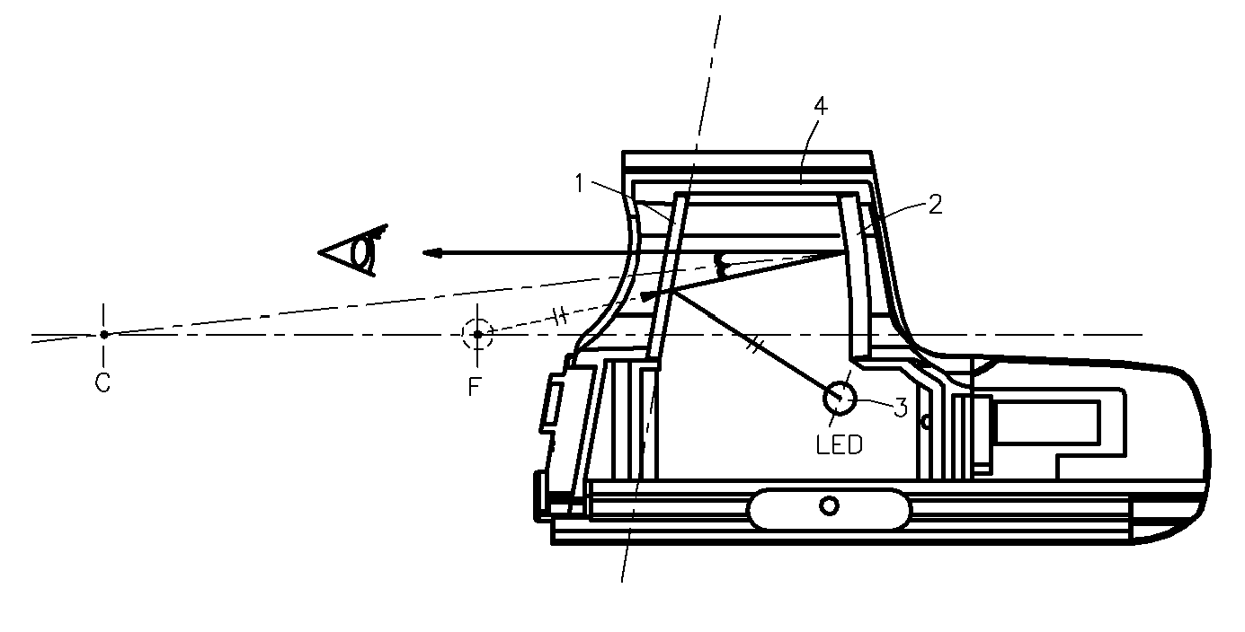
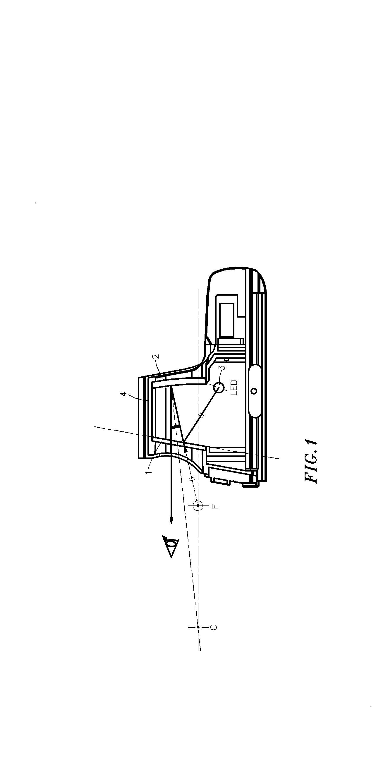
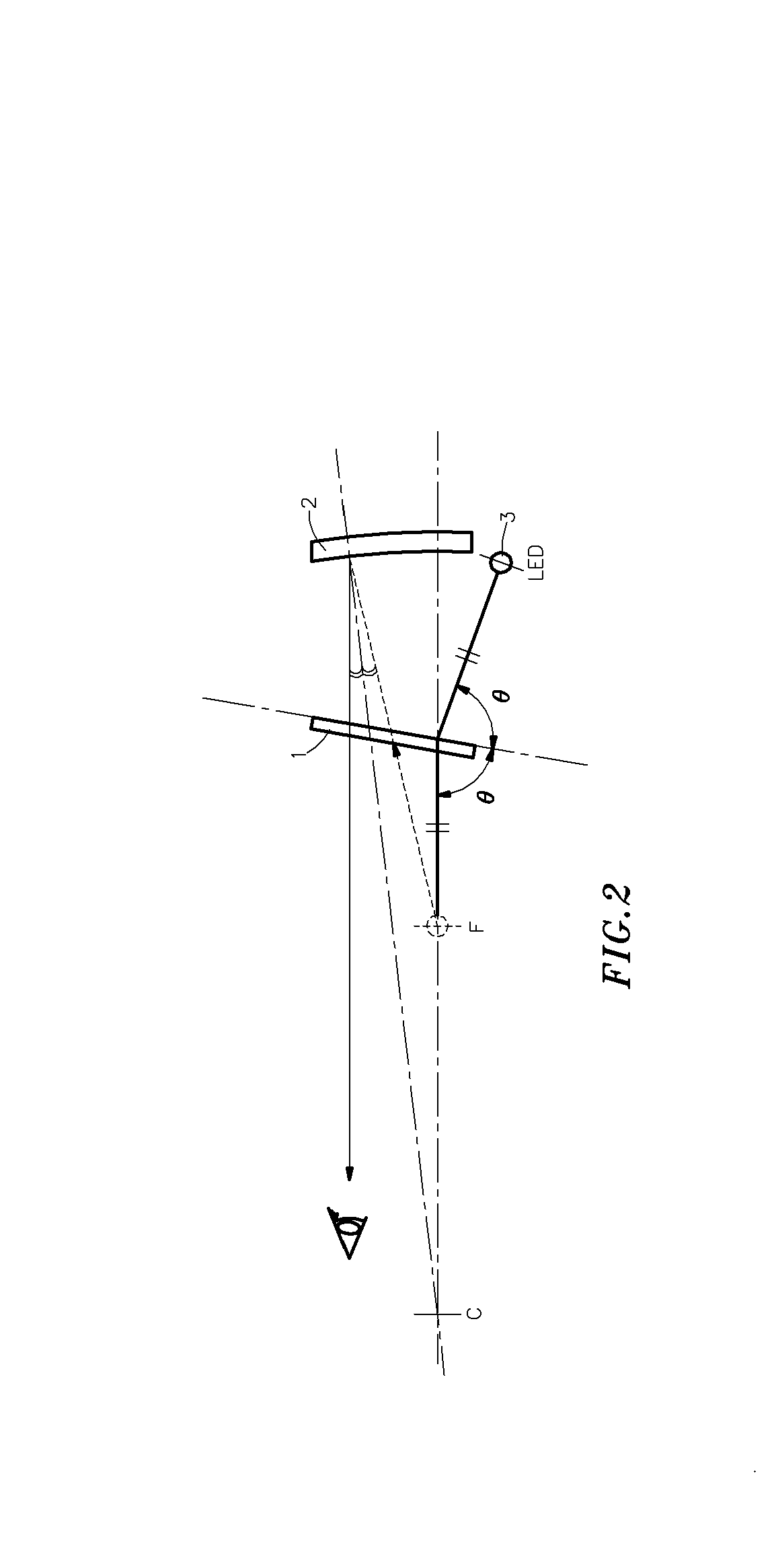
[0016]Referring to FIGS. 1 and 2, an internal red dot sight 4 is shown comprised of an eye lens 1, an objective lens 2, and a light emitting device 3 adapted to emit light in between the eye lens 1 and the objective lens 2. The eye lens 1 is a planar lens. The objective lens 2 is a concave lens. The eye lens 1 is set in a tilt angle relative to the objective lens 2. When the light emitting device 3 is operated to emit light toward the eye lens 1, the eye lens 1 reflects a point light source of the light emitting device 3, thereby forming a virtual point light source on an major axis of the objective lens 2 subject to the law that incident angle=angle of reflection. At this time, this distance between the point light source of the light emitting device 3 and the eye lens 1 is equal to the distance between the virtual point light source and the eye lens 1. Therefore, the virtual point light source is allocated at a focal point F of the objective lens 2, and a light ray is projected to...


PUM


Abstract

An internal red dot sight includes an objective lens formed of a convex lens, a planar eye lens set in a tilt angle relative to the objective lens and facing the concave surface of the objective lens, and a light emitting device set in between the planar eye lens and the objective lens and controlled to emit a point light source onto the eye lens for enabling the eye lens to reflect the point light source and to further produce a virtual point light source on the focal point of the objective lens for viewing by the user.

Description

BACKGROUND OF THE INVENTION[0001]1. Field of the Invention[0002]The present invention relates to a sight for use in a gun or the like to guide the eyes and more particularly, to an internal red dot sight, which projects a virtual point light source onto the objective lens, simulating the parallel emission of a point light source from a remote site and, which employs coating techniques to control the percentage of red light reflection, achieving the objects of shortening the length of the internal red dot sight, increasing the size of the objective lens, reducing the manufacturing cost of the internal red dot sight, and improving the projection precision of the light source.[0003]2. Description of the Related Art[0004]Conventional sights for use in guns to guide the eyes include two types, namely, the internal red dot type and the external red dot type. In a battle, the sight helps the fighter to achieve fast target acquisition. A regular external red dot sight uses a laser pointer t...

Claims


Application Information

Patent Timeline
Patent Type & Authority Patents(United States)
IPC IPC(8): F41G1/00
CPCF41G1/345
Inventor CHENG, LI-DERLEE, YI-RONG
Owner CHENG LI DER
Learn More