Stereoscopic display

a stereoscopic display and parallax technology, applied in the field of parallax stereoscopic displays, can solve the problems of difficult to provide a haptic interface, inability to display stereoscopic videos including moving images, and inability for viewers to enter the display space, so as to reduce the effective pitch, increase the number of horizontal pixels, and reduce the effect of effective pitch

Inactive Publication Date: 2007-06-19
SEIKO EPSON CORP
View PDF31 Cites 9 Cited by
  • Summary
  • Abstract
  • Description
  • Claims
  • Application Information

AI Technical Summary

Benefits of technology

[0044]Accordingly, the number of slits, that is, the number of horizontal pixels, can be increased by reducing the effective pitch. Therefore, a stereoscopic moving image with increased definition can be obtained.
[0045]Accordingly, the stereoscopic display of the present invention is able to reproduce a high-quality stereoscopic moving image in space. More specifically, the present invention provides a stereoscopic display which is capable of displaying a natural, color-filled, stereoscopic moving image providing a feeling which can also be reproduced.

Problems solved by technology

Accordingly, electronic stereoscopic videos including moving images cannot be displayed.
In addition, in the method of reproducing the multi-viewpoint light beams around the entire periphery, since a cylindrical barrier is disposed around the space in which the stereoscopic image is formed, it is not possible for viewers to enter the display space.
Therefore, it is difficult to provide a haptic interface and interactiveness with the viewers is limited.
In addition, due to the existence of a parallax barrier and a protective cover which is necessary to prevent the viewers from directly touching a rotator and slits, it has been impossible to form a stereoscopic image in the true sense.

Method used


Image

  • Stereoscopic display
  • Stereoscopic display
  • Stereoscopic display

Examples


first embodiment

[0060

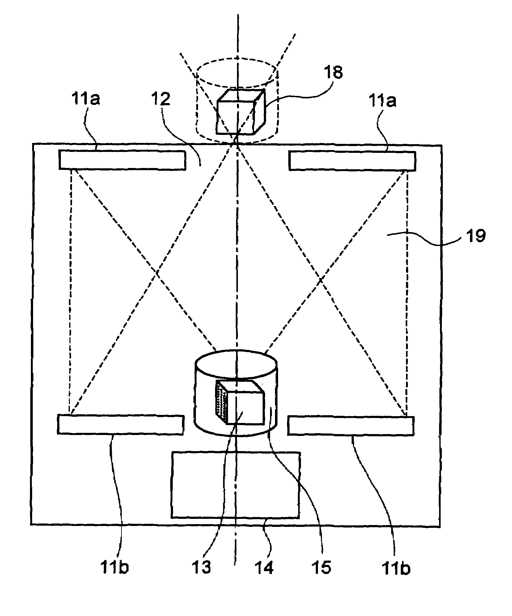
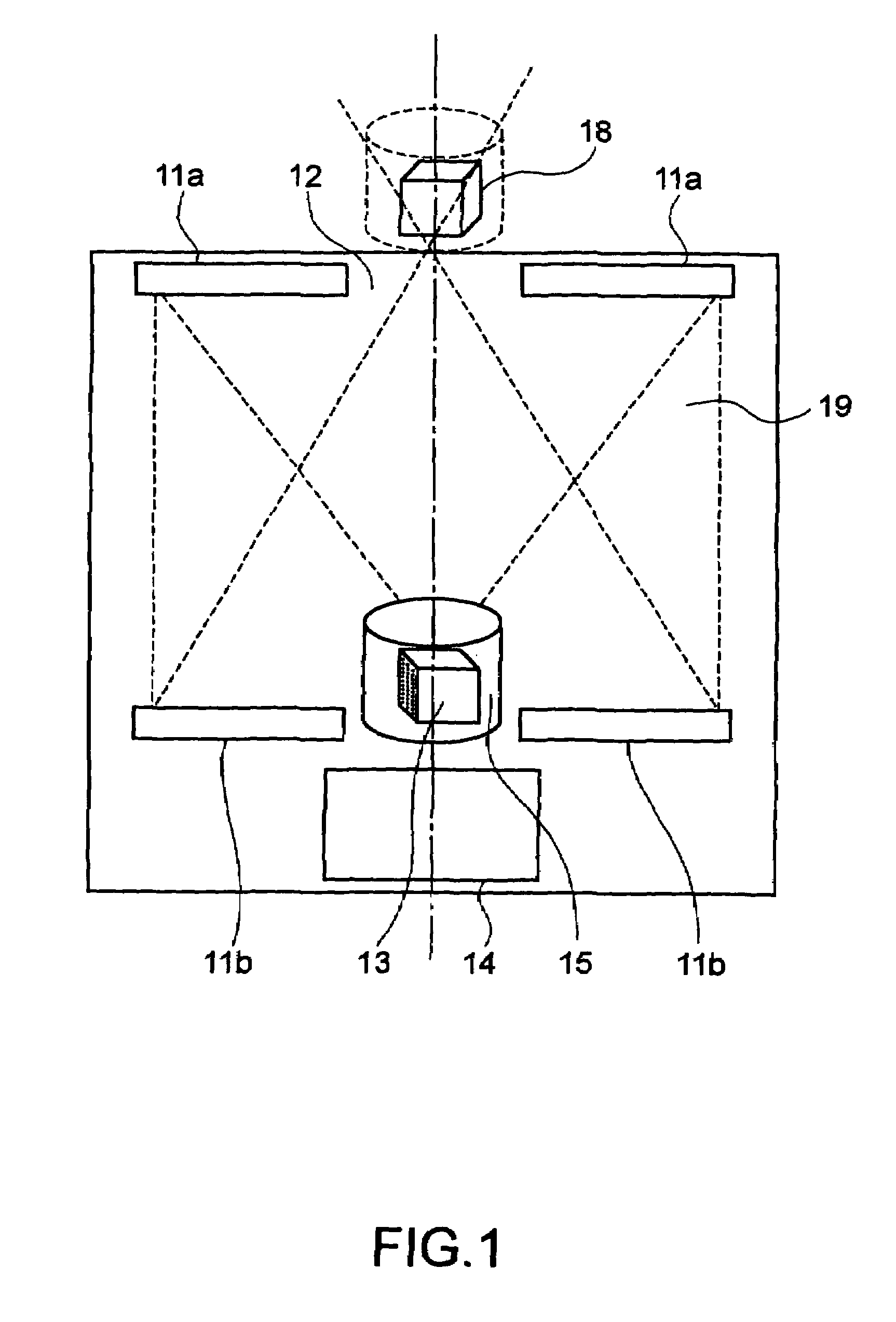
[0061]FIG. 1 is a schematic showing a construction in which a reflective image-forming optical system is used as an image-forming device and a cylindrical parallax barrier 15 and a rotating cylindrical light-emitting array are used together as a multi-viewpoint-light-beam forming device.

[0062]In the reflective image-forming system, two Fresnel mirrors 11a and 11b, which are reflective optical elements which serve as convex lenses, are disposed such that the Fresnel mirrors 11a and 11b oppose each other. Apertures 12 are formed in the Fresnel mirrors 11a and 11b at the central regions thereof. A stereoscopic image 13, which is reproduced by a multi-viewpoint light beam group formed by the light-emitting array and the cylindrical parallax barrier 15, is placed close to the lower aperture, and a conjugate image 18 is formed at a position close to the upper aperture. Accordingly, the conjugate image 18, which is to be observed by a viewer, is formed by the lower Fresnel mirror 11b,...

second embodiment

[0075

[0076]FIG. 8 is a schematic showing a construction in which a reflective image-forming optical system is used as an image-generating device, a cylindrical slit-formed unit and a rotating light-emitting array are used together as a multi-viewpoint-light-beam-group forming device, and a polarization selecting element and a phase plate are disposed between the multi-viewpoint-light-beam-group forming device and a conjugate image.

[0077]The stereoscopic display according to the present embodiment includes a stereoscopic image 81 reproduced by a multi-viewpoint light beam group, image-forming optical elements 82a and 82b which form the reflective image-forming device and serve as convex lenses, a reflection / polarization selecting element 83 which separates polarized light used to form a conjugate image 88, a phase plate 84, and a mirror 85. An upper polarizing element 86 is provided as necessary so that reflection of external light at the reflection / polarization selecting element 83 ...

third embodiment

[0086

[0087]FIG. 10 is a schematic of a multi-viewpoint-light-beam generating device used in the present embodiment. FIG. 11 is a perspective view of a cylindrical light-emitting array shown in FIG. 10.

[0088]The multi-viewpoint-light-beam generating device 100 includes a cylindrical parallax barrier 102 disposed at the periphery and a cylindrical light-emitting array 101 disposed inside the cylindrical parallax barrier 102. As shown in FIG. 11, the cylindrical light-emitting array 101 is formed such that two-dimensional light-emitting-array elements 111 are arranged so as to cover almost the entire periphery thereof.

[0089]The two-dimensional light-emitting-array elements 111 are preferably formed of thin-film light-emitting elements. A single light-emitting-array element includes 768×128 pixels, and twelve light-emitting-array elements are disposed at the periphery of the cylindrical body. More specifically, the light-emitting-array elements are formed of active-matrix, thin-film, or...


PUM


Abstract

The invention provides a stereoscopic display to display a high-quality three-dimensional video which can be viewed without using polarizing glasses. A stereoscopic display according to the present invention includes an electronically-formed, multi-viewpoint light beam group and an image-forming device to reproduce a conjugate image of the multi-viewpoint light beams. The stereoscopic display further includes a cylindrical, or partially cylindrical parallax barrier and a rotating light-emitting array as a multi-viewpoint-light-beam forming device. In addition, the stereoscopic display further includes a polarizing element and a polarization separation device to increase the display contrast. The numerical aperture of the rearmost optical element is preferably increased in order to increase the viewing area, and a reflective optical element with a large aperture is used as the image-forming device. The light-emitting array is formed of lightweight, thin-film light-emitting elements with which electronic rotational scanning is possible.

Description

BACKGROUND OF THE INVENTION[0001]1. Field of the Invention[0002]The present invention relates to parallax stereoscopic displays. More specifically, the invention relates to a stereoscopic display to display a color 3-dimensional moving image which can be viewed without using polarizing glasses or liquid crystal shutters.[0003]2. Description of the Related Art[0004]Conjugate-image-reproducing stereoscopic displays using concave mirrors or convex lenses, which are disclosed in U.S. Pat. Nos. 2,628,533, 3,647,284, and 5,508,763, can be used to display stereoscopic images easily.[0005]The related art also includes stereoscopic displays known as “binocular type” displays. In addition, a display in which multi-viewpoint light beams are generated by rotational scanning so that an image can be seen from 360 degrees is disclosed in 3D Image Conference 1999, Paper No. 4—4.SUMMARY OF THE INVENTION[0006]However, in the related art conjugate-image-reproducing stereoscopic displays, since a conju...

Claims


Application Information

Patent Timeline
Patent Type & Authority Patents(United States)
IPC IPC(8): G02B27/22G03B35/26G02B30/25G02B30/30H04N13/393
CPCG02B27/2214G02B27/225H04N13/0409H04N13/0422H04N13/0493H04N13/0434H04N13/0438H04N13/0497H04N13/337H04N13/341H04N13/324H04N13/393H04N13/31H04N13/398G02B30/30G02B30/27
Inventor SONEHARA, TOMIO
Owner SEIKO EPSON CORP
Why Eureka
Try Eureka