
Imaging apparatus utilizing image pickup devices used for an interlaced scanning

Inactive Publication Date: 2007-06-19
SONY CORP
View PDF4 Cites 5 Cited by
  • Summary
  • Abstract
  • Description
  • Claims
  • Application Information

AI Technical Summary

Benefits of technology

[0006]It is, therefore, an object of the invention to provide an imaging apparatus for easily generating image signals on a progressive scanning basis.
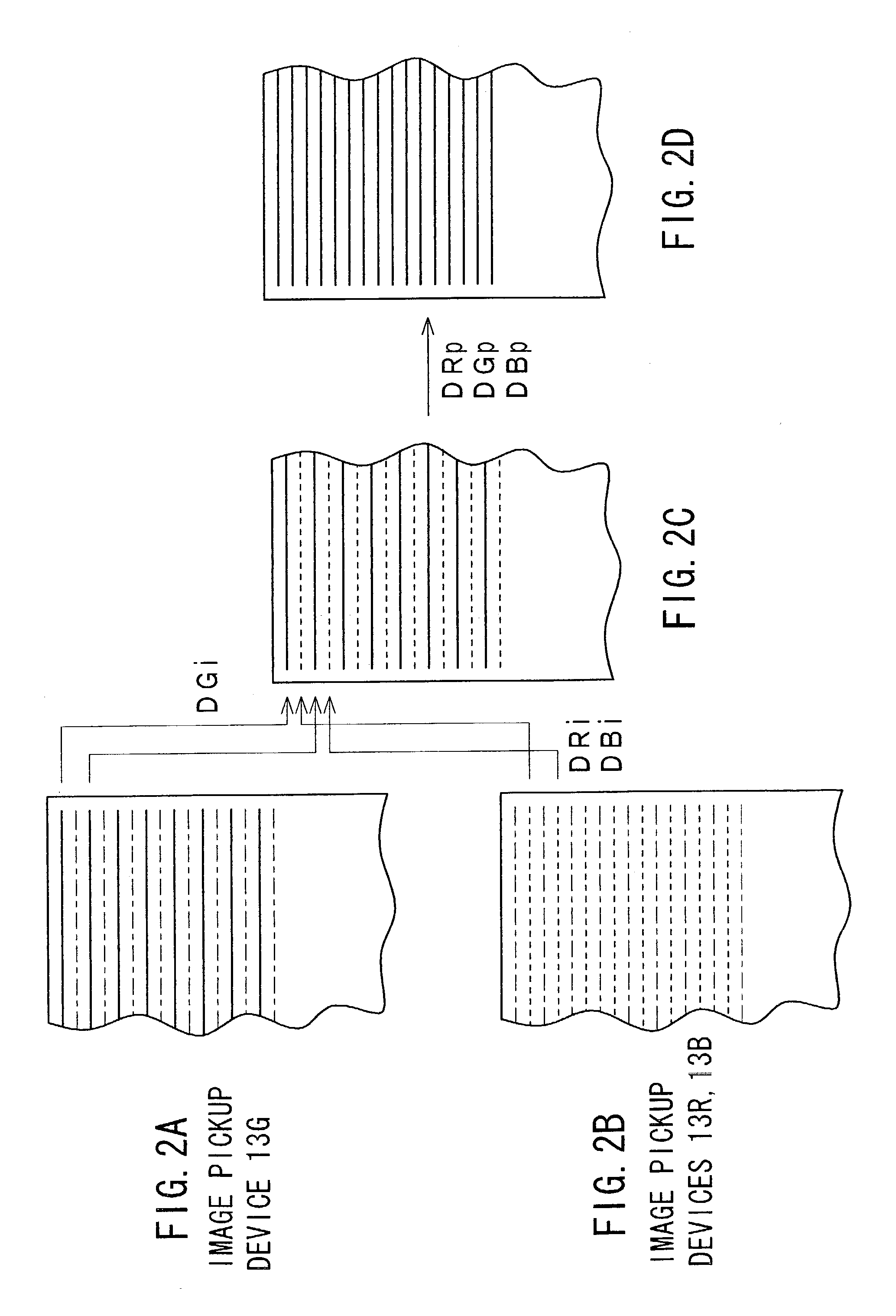
[0009]According to the invention, at least one of the multiple image pickup devices and at least one of the remaining image pickup devices are driven in opposite interlace fields to generate image signals on an interlaced scanning basis. For example, the image pickup devices are driven so that at least one of a red signal and a blue signal, and a remaining green signal can be generated from the image pickup devices according to the opposite interlace fields. Then, the image signals with opposite interlace fields are interpolated into each other, thereby generating image signals on a progressive scanning basis. This allows the image signals to be generated on the progressive scanning basis using image pickup devices used for the interlaced scanning without any image pickup devices used for a progressive scanning. Therefore, this prevents operating frequencies of the image pickup devices from increasing and avoids causing a wide band signal processing circuit to easily implement an imaging apparatus used for the progressive scanning.
[0010]Low-frequency and high-frequency components of the green signal are respectively generated on the progressive scanning basis from the green signal generated on the interlaced scanning basis. Similarly, low-frequency and high-frequency components of red and blue signals are respectively generated on the progressive scanning basis from the red and blue signals generated on the interlaced scanning basis. The high-frequency components of the green, red and blue signals are used to generate a luminance-interpolating component to be added to the respective low-frequency components of the respective chrominance signals, thereby generating image signals on the progressive scanning basis. The use of such the frequency-divided image signals allows information in the image signals generated on the interlaced scanning basis to be successfully reproduced in the image signals generated on the progressive scanning basis.
[0012]When a shutter operation is to be performed, an appropriate exposure time of the shutter is set for the period of the predetermined number of frames. The image pickup devices then output image signals generated on the interlaced scanning basis in response to the exposure time. This allows the imaging apparatus to provide an outstanding image without any false frames.

Problems solved by technology

This makes it difficult to compose a simple and inexpensive imaging apparatus.
As a consequence, a signal processing circuit for processing the image pickup devices and the signals read out of them must be operable at a high speed, thus resulting in extra increases of power consumption and a manufacturing cost.
It, however, is difficult to operate the driving circuit and the signal processing circuit at quite different reference operating frequencies like this.
Provision of two separate sets of a drive circuit and a signal processing circuit, one for the interlace scanning and another for the progressive scanning, in one imaging apparatus requires a large area for the circuits, which hinders miniaturization and cost cutting of an imaging apparatus.

Method used


Image

  • Imaging apparatus utilizing image pickup devices used for an interlaced scanning
  • Imaging apparatus utilizing image pickup devices used for an interlaced scanning
  • Imaging apparatus utilizing image pickup devices used for an interlaced scanning

Examples


Embodiment Construction

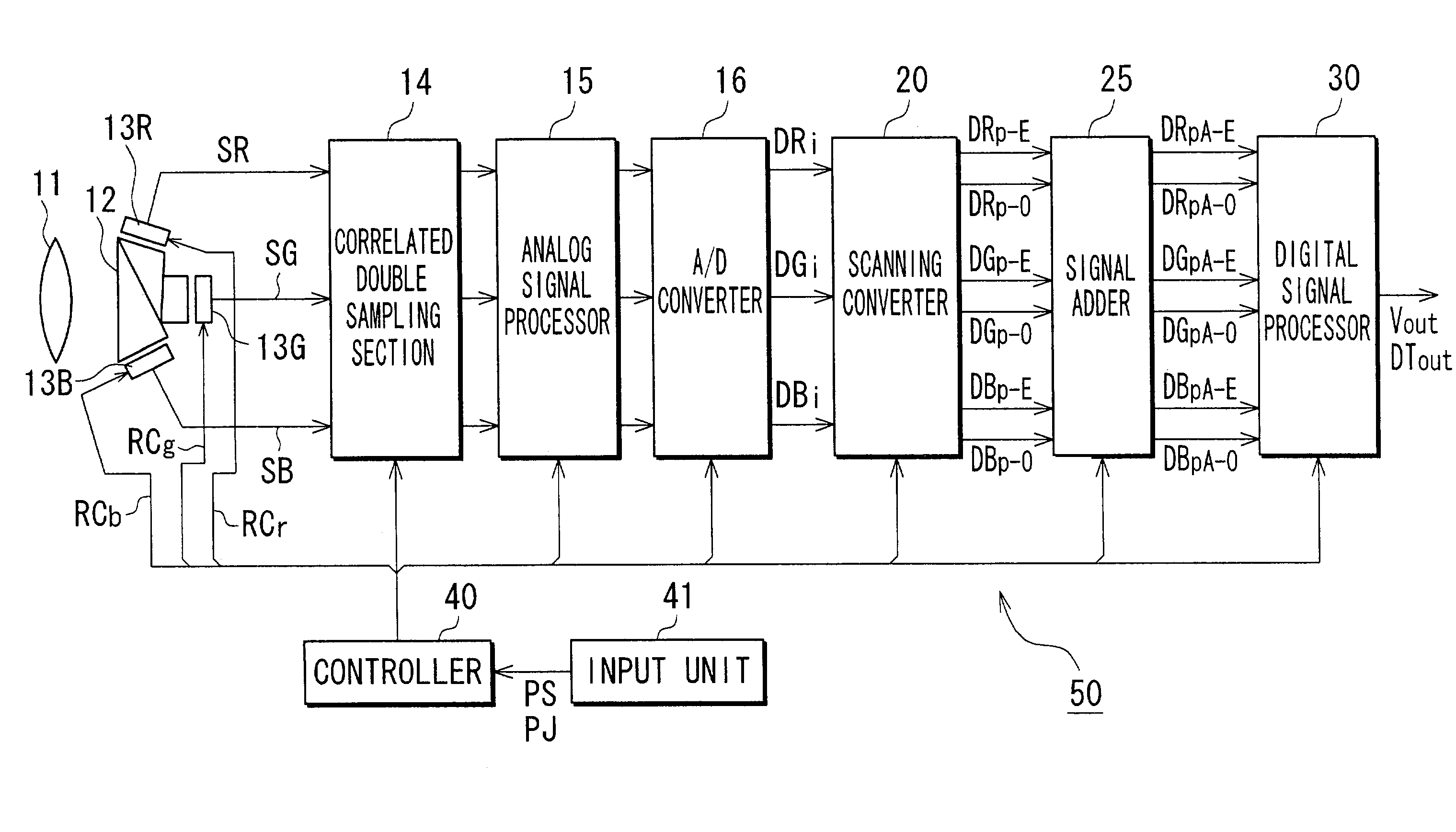
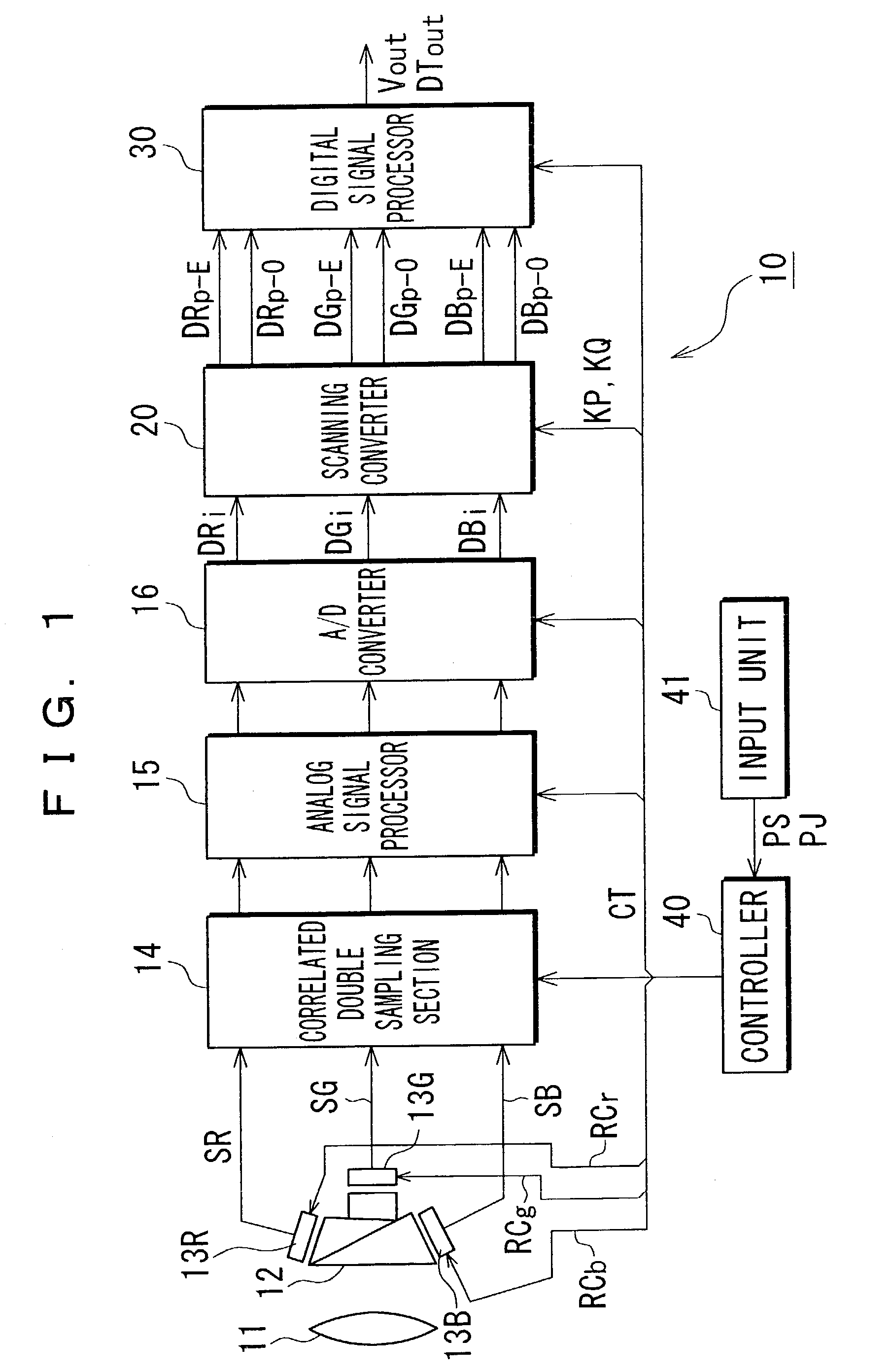
[0025]FIG. 1 shows a configuration of an imaging apparatus 10 of the invention utilizing an optical unit for RGB color separation and three charge-coupled devices (CCDs).

[0026]An incident beam of light emitted from an object enters into a color separation prism 12 via an image pickup lens system 11. The color separation prism 12 is provided on the red component exit face thereof with a CCD used for an interlace scanning that serves as an image pickup device 13R. The prism 12 is also provided on the green and blue component exit faces thereof with CCDs used for the interlace scanning that serve as a green and a blue image pickup devices 13G and 13B, respectively.

[0027]The image pickup device 13R drives and reads out electrical charge formed by the red component of the incident light through photoelectric conversion, under the control of a drive signal RCr supplied from a controller 40, which will be described later. The image pickup device 13R generates a red signal SR. A correlated ...


PUM


Abstract

The invention provides a convenient way of generating image signals on a progressive scanning basis. Multiple image pickup devices used for an interlaced scanning drive and generate chrominance signal DGi on the interlaced scanning basis with an interlace field and chrominance signals DRi and DBi on the interlaced scanning basis with opposite interlace field. Scanning converter receives the chrominance signal Dgi, DRi and Dbi. The scanning converter then performs an interpolation based on the chrominance signals DGi, DRi, and DBi to generate corresponding chrominance signals DGp (DGp-E, DGp-O), DRp (DRp-E, DRp-O), and DBp (DBp-E, DBp-O) on a progressive scanning basis. Signal processor receives the resultant chrominance signals DGp, DRp, and DBp. The scanning converter sums the chrominance signals DGp, DRp, and DBp belonging to a predetermined number of frames to obtain a new set of chrominance signals.

Description

FIELD OF THE INVENTION[0001]The invention relates to an imaging apparatus for generating image signals on a progressive scanning basis utilizing image pickup devices used for an interlace scanning.DESCRIPTION OF RELATED ART[0002]In recent years, image signals on a progressive scanning basis have been used in addition to image signals on an interlaced scanning basis in order to provide an extended definition picture. Use of the image signals on the progressive scanning basis prevents lowering of perpendicular resolution of an image caused by the interline flickers.[0003]In the progressive scanning, however, when interline transfer (IT) typed charge coupled devices (CCDs) or frame interline transfer (FIT) typed CCDs, for example, are used as the image pickup devices, the number of the perpendicular transfer registers (TFRs) for reading electrical charge generated by photo sensors through photoelectric conversion must be doubled as compared with the one used for the interlaced scanning...

Claims


Application Information

Patent Timeline
IPC IPC(8): H04N3/14H04N5/235H04N5/238H04N5/335H04N9/68H04N5/232H04N7/01H04N9/04H04N9/09
CPCH04N5/3452H04N7/012H04N9/045H04N2209/046H04N25/441H04N23/843
Inventor KAMEYAMA, TAKASHIAKAZAWA, SYUICHI
Owner SONY CORP
Learn More