
Differential encoding

Inactive Publication Date: 2007-06-05
SONY UK LTD
View PDF7 Cites 30 Cited by
  • Summary
  • Abstract
  • Description
  • Claims
  • Application Information

AI Technical Summary

Benefits of technology

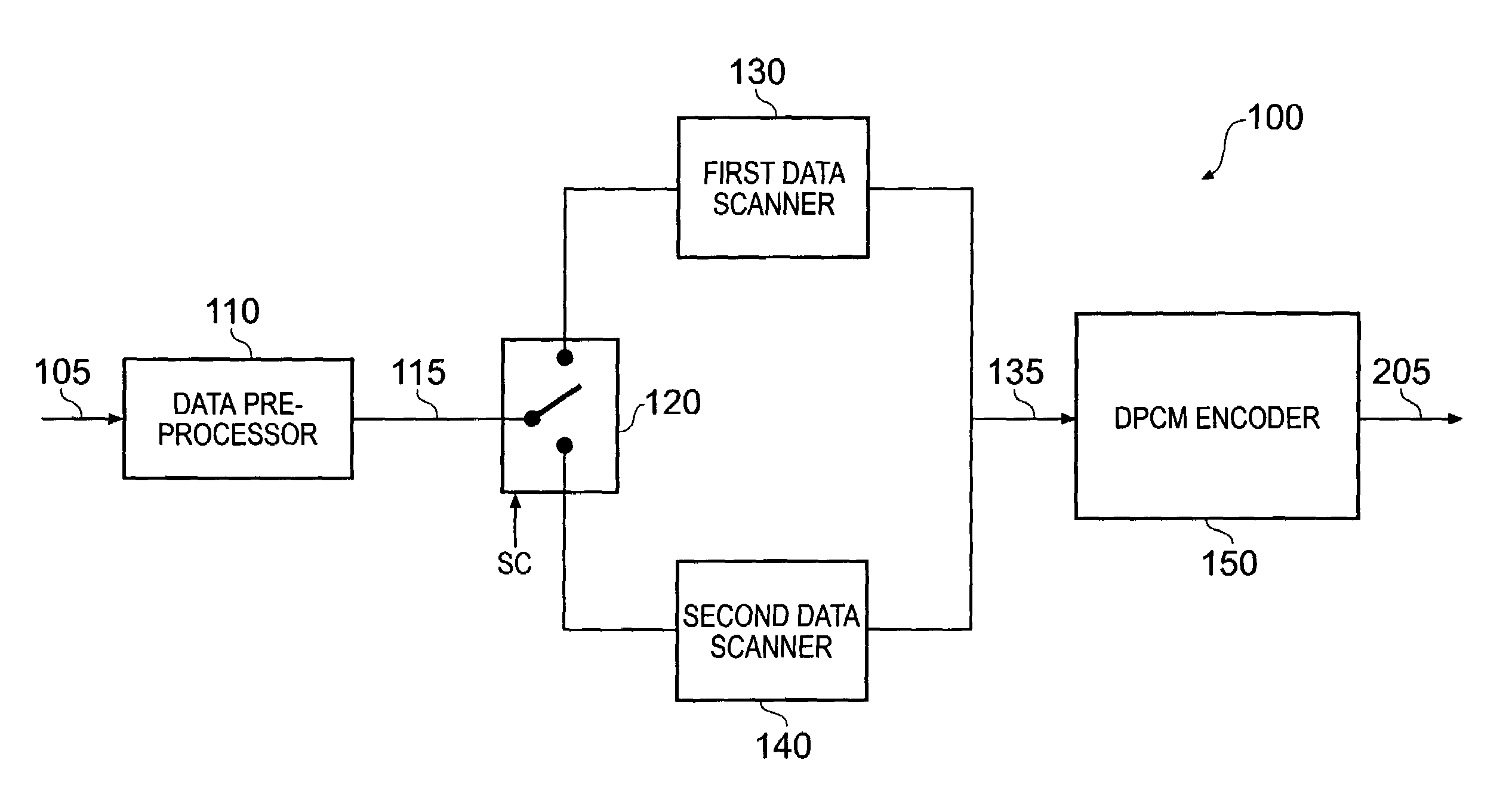
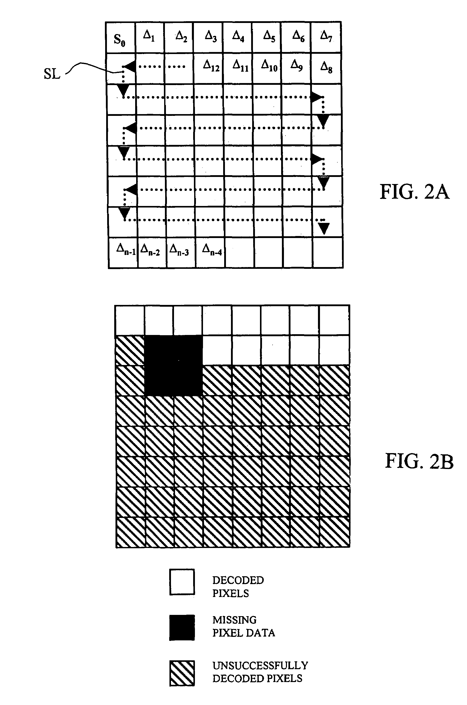
[0016]The invention addresses this problem by providing at least two different orders of encoding dependency, each applicable to a subset of images. In this way, the pixels which are most likely to suffer in the event of data loss are varied from image to image. This can mean that pixels at various positions in an image region can be successfully decoded in different images, so allowing temporal concealment to be used more effectively.
[0017]The feature that the first and second subsets of images are arranged with respect to one another so that, from image to image, each image region is encoded in accordance with a predetermined sequence (e.g. a repeating sequence) of orders of encoding dependency can simplify the arrangements needed at decoding to detect which order of encoding dependency has been used.
[0018]Preferably the predetermined sequence is such that, for each pair of consecutive images, an image region is encoded using different orders of encoding dependency. This gives a more robust system in difficult decoding conditions, such as during shuttle replay in a tape-based system, in that it allows different parts of an image region to be decoded in successive images. This in turn can improve the concealment of unsuccessfully decoded pixels.
[0019]For elegant simplicity and ease of decoding, preferably the first and second subsets comprise complementary sets of alternate images, such as alternate fields of an interlaced video signal.
[0020]To give a greater difference between encoding modes in order to reduce the effects of missing pixels, it is preferred that the reference values in the first encoding mode and the reference values in the second encoding mode respectively represent pixels at different spatial positions within the image regions. Indeed, it is preferred that the reference values in the first encoding mode and the reference values in the second encoding mode respectively represent pixels at substantially opposite peripheral positions within the image regions.
[0026]Preferably the concealment logic comprises means for detecting whether the previously decoded pixels were validly decoded; and the means for applying is operable not to apply a concealment value to replace a current invalidly decoded pixel if the previously decoded pixel(s) used to generate that concealment value were not validly decoded. This avoids concealing pixels on the basis of earlier invalidly decoded pixels.

Problems solved by technology

This would mean that if data errors were encountered in such previous systems, it would always be the same part of the image region (in the example, the bottom-right portion) which would be unsuccessfully decoded.

Method used


Image

  • Differential encoding
  • Differential encoding
  • Differential encoding

Examples


second embodiment

[0077]FIG. 9 schematically illustrates a decoder. In this embodiment, validity data is stored with the pixel data indicating whether the pixels have been correctly decoded. This validity data is used to control whether a newly decoded pixel should be stored in the frame stores, or whether a corresponding pixel from a previous field or frame should be used instead.

[0078]In this embodiment the DPCM decoder 210′ generates two outputs: pixel data and associated validity data indicating whether the pixel data was correctly decoded from the input data stream. The pixel data is supplied to a multiplexer, 230′, and the validity data is supplied to control logic 310 which controls the operation of the multiplexer 230′. The multiplexer 230′ receives, as a second input, fed-back pixel data from a set of frame stores 320, and the control logic 310 receives, as a second input, fed-back validity data from the frame stores 320.

[0079]The fed-back pixel and validity data are derived from correspondi...

third embodiment

[0092]FIG. 15 schematically illustrates decoder. In many respects this is similar in operation to the decoder of FIG. 9, and so only the differences will be described.

[0093]As part of the fed-back data associated with each pixel, a timestamp is also provided. Timestamps were mentioned above, and their storage in association with the pixel data was described. The purpose of the timestamp is to allow the system to limit number of frames over which a pixel is re-used. Basically, the timestamp can take one of two main forms: (a) an indication of the field or frame at which that pixel was first stored in the frame store 320, or (b) a running counter, incremented each frame, showing how long that pixel has been stored. In the first case, the timestamp can be compared with a current time to determine how long a pixel has been re-used. In the second case, which is the preferred embodiment to be described here, the timestamp starts at zero, is incremented each time a pixel is re-stored, and ...


PUM


Abstract

An encoding apparatus operable to encode video data representing successive images, each image including a plurality of pixels. The apparatus includes a differential encoder arranged to encode each image as one or more predetermined image regions. Each image is being encoded as a reference value and at least one differential pixel value. The differential pixel value(s) are derived in dependence on the reference value and / or other differential pixel value(s) in accordance with an order of encoding dependency; in which, for each image region, the differential encoder is operable in a first encoding mode for a first subset of the images to encode the image region using a first order of encoding dependency and in a second encoding mode for a second, different, subset of the images to encode the image region using a second, different, order of encoding dependency. The first and second subsets of images are arranged with respect to one another so that, from image to image, each image region is encoded in accordance with a predetermined sequence of orders of encoding dependency.

Description

BACKGROUND OF THE INVENTION[0001]1. Field of the Invention[0002]This invention relates to differential encoding.[0003]2. Description of the Prior Art[0004]Differential encoding processes for encoding data such as Differential Pulse Code Modulation (DPCM) are well known and described for example in M. J. Riley and I. E. G. Richardson, “Digital Video Communications”, Artech House Inc., 1997. Differential encoding processes are often used to encode image data but are applicable to any type of electronic data.[0005]In one form of DPCM, a current pixel may be encoded either as a reference pixel value which is a direct representation of the pixel value, or as a differential pixel value. An image region may be represented by a reference pixel value and a group of one or more difference values. A difference value is determined from the reference pixel value and intermediate difference values, following an order of encoding dependency. Thus, an image region might have, for example, its top-l...

Claims


Application Information

Patent Timeline
Patent Type & Authority Patents(United States)
IPC IPC(8): H04N7/12H04N5/92H03M7/36H04N1/417H04N19/89H04N19/895
CPCH04N19/176H04N19/593H04N19/895H04N19/85H04N19/89
Inventor PORTER, ROBERT MARK STEFANSAUNDERS, NICHOLAS IANPELLY, JASON CHARLES
Owner SONY UK LTD
Learn More