
Method and system for control system software

a technology of control system and touch panel, applied in static indicating devices, instruments, animations, etc., can solve problems such as misoperation of the touch panel system

Active Publication Date: 2007-05-29
HARMAN PROFESSIONAL INC
View PDF245 Cites 63 Cited by
  • Summary
  • Abstract
  • Description
  • Claims
  • Application Information

AI Technical Summary

Benefits of technology

[0008]In a further embodiment, each of the graphical display units is selectively provided with one or more colors, and is further provided with one or more features selected from a group of features that includes a bitmap, an icon, text and a border. Preferably, one or more sub-pages are configured in association with the page, at least one of the sub-pages comprising a video feed. Prefe

Problems solved by technology

A problem arises, however, when multiple buttons are displayed on the touch panel in close proximity to each other.
This causes either an error to occur with the touch panel, or the touch panel itself prioritizes the buttons and selects the button with the higher priority to operate, often resulting in misoperation of the touch panel system.

Method used


Image

  • Method and system for control system software
  • Method and system for control system software
  • Method and system for control system software

Examples


Embodiment Construction

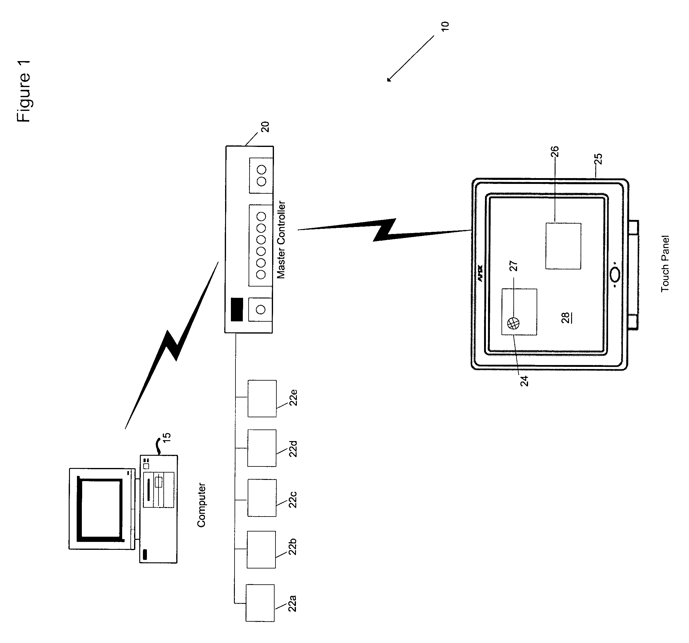
[0033]FIG. 1 shows the interactions and communications between components of a control system 10, wherein the system 10 includes one or more computers 15 in communication with one or more master controllers 20. The master controller 20 is in communication with one or more touch panels 25. The touch panels 25 may be desktop touch panels or wall display units. The master controller 20 may be attached to various components, so that respective components may be controlled by the control system 10 through master controller 20. These components may include, but are not limited to, lighting fixtures 22a, alarm systems 22b, video equipment 22c, household electronics equipment 22d, security systems 22e, and the like.

[0034]A user utilizes the computer 15 to create touch panel displays such as 24 and 26 for display by the touch panel. These touch panel displays can be configured to control components 22a–e of the type referred to above. More particularly, a touch panel display comprises or con...


PUM


Abstract

The present invention discloses a method for building and displaying control and non-interactive, non-control information on a touch panel. The method can include constructing a page for display on the touch panel, configuring one or more graphical display units and one or more sub-pages for display on the page, and displaying the page, graphical display units and sub-pages, selectively, on the touch panel. The method further includes determining whether any of the graphical display units is activated by a touch message applied to a location on the touch panel. Respective graphical display units may be selectively provided with features from a group of features that includes bitmaps, icons, borders and text. Two graphical display units having respective active touch areas may be displayed on the touch panel so that their active touch areas are separated by no more than one pixel.

Description

TECHNICAL FIELD OF THE INVENTION[0001]The present invention relates to methods for displaying user control information on a touch panel and more particularly, the present invention relates to methods for building interactive control and non-interactive, non-control informational displays onto a touch panel screen.BACKGROUND OF THE INVENTION[0002]Touch panels are electronic devices that use liquid crystal displays (LCDs) to display functional information to a user. A touch panel is used to operate various pieces of equipment. For example, touch panels can be used to control the lighting system of a room, electronics equipment such as VCRs, DVDs, stereos, and the like, and video surveillance equipment, such as video cameras, and other similar types of equipment.[0003]A touch panel operates by allowing the user to press a region of the LCD panel to operate an associated piece of equipment. The user knows the region of the LCD to touch because an informational display (sometimes referre...

Claims


Application Information

Patent Timeline
IPC IPC(8): G06T13/00G06F3/048G09G5/00H01Q11/12H04B1/40H04B7/00H04M7/04
CPCG06F3/04842
Inventor KESSLER, JOSEPHLEE, MARK R.PITTANA, ROBERT
Owner HARMAN PROFESSIONAL INC
Learn More