Reclining device and method of locking the device
a technology of locking device and reclining mechanism, which is applied in the direction of movable seats, vehicle components, vehicle arrangements, etc., can solve the problems of increasing size, weight and manufacturing cost of reclining mechanism, tooth slippage, and limited relative rotation of both housings, so as to improve the locking performance of the conventional reclining mechanism without increasing the spring force
- Summary
- Abstract
- Description
- Claims
- Application Information
AI Technical Summary
Benefits of technology
Problems solved by technology
Method used
Image
Examples
first embodiment
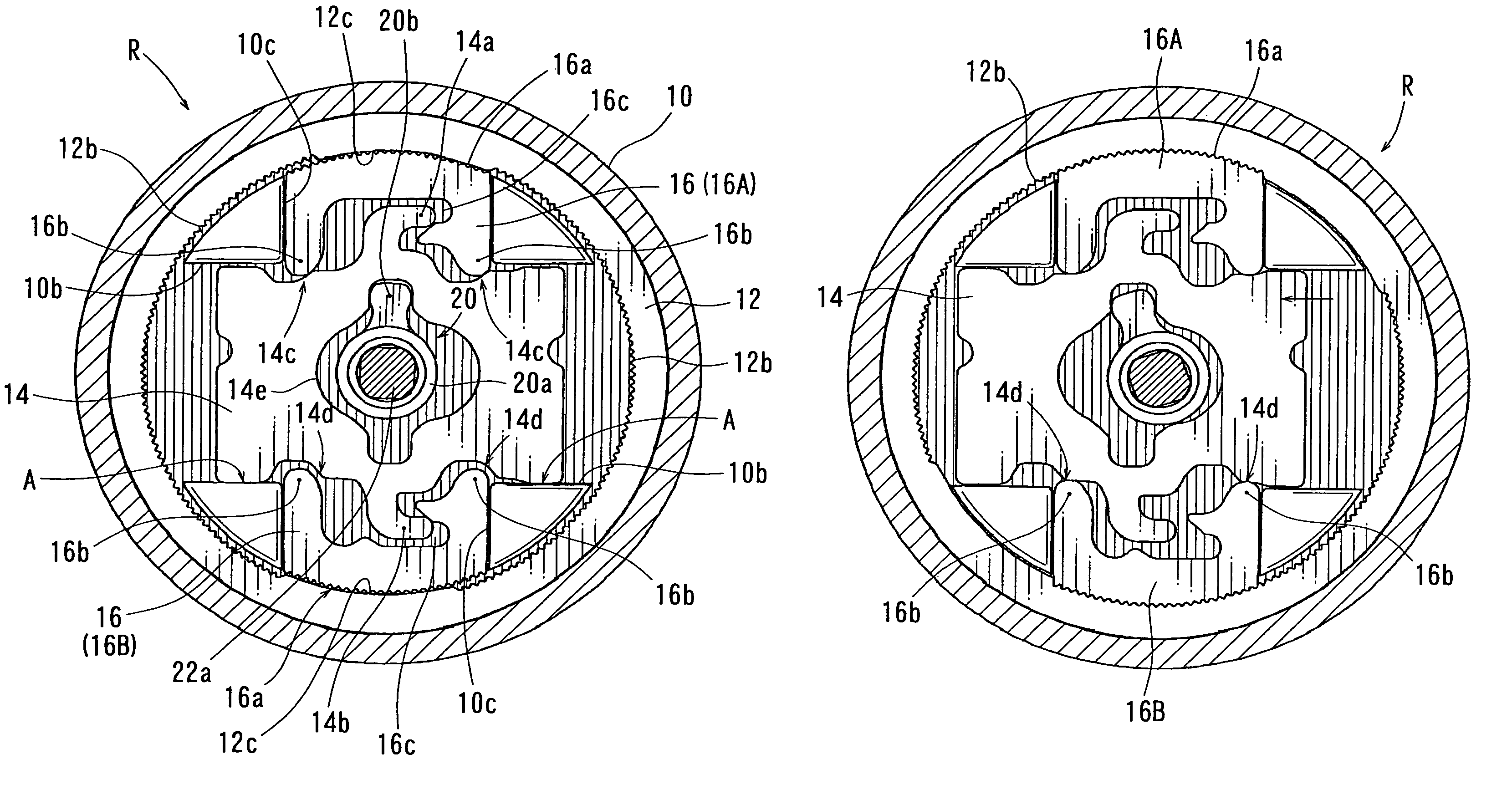
[0026]Hereinafter, embodiments of the present invention will be described. A first embodiment will be described with reference to FIGS. 1 to 7.
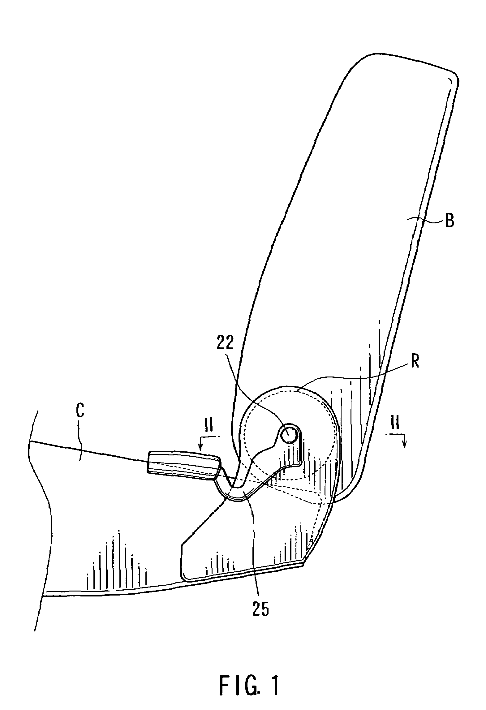
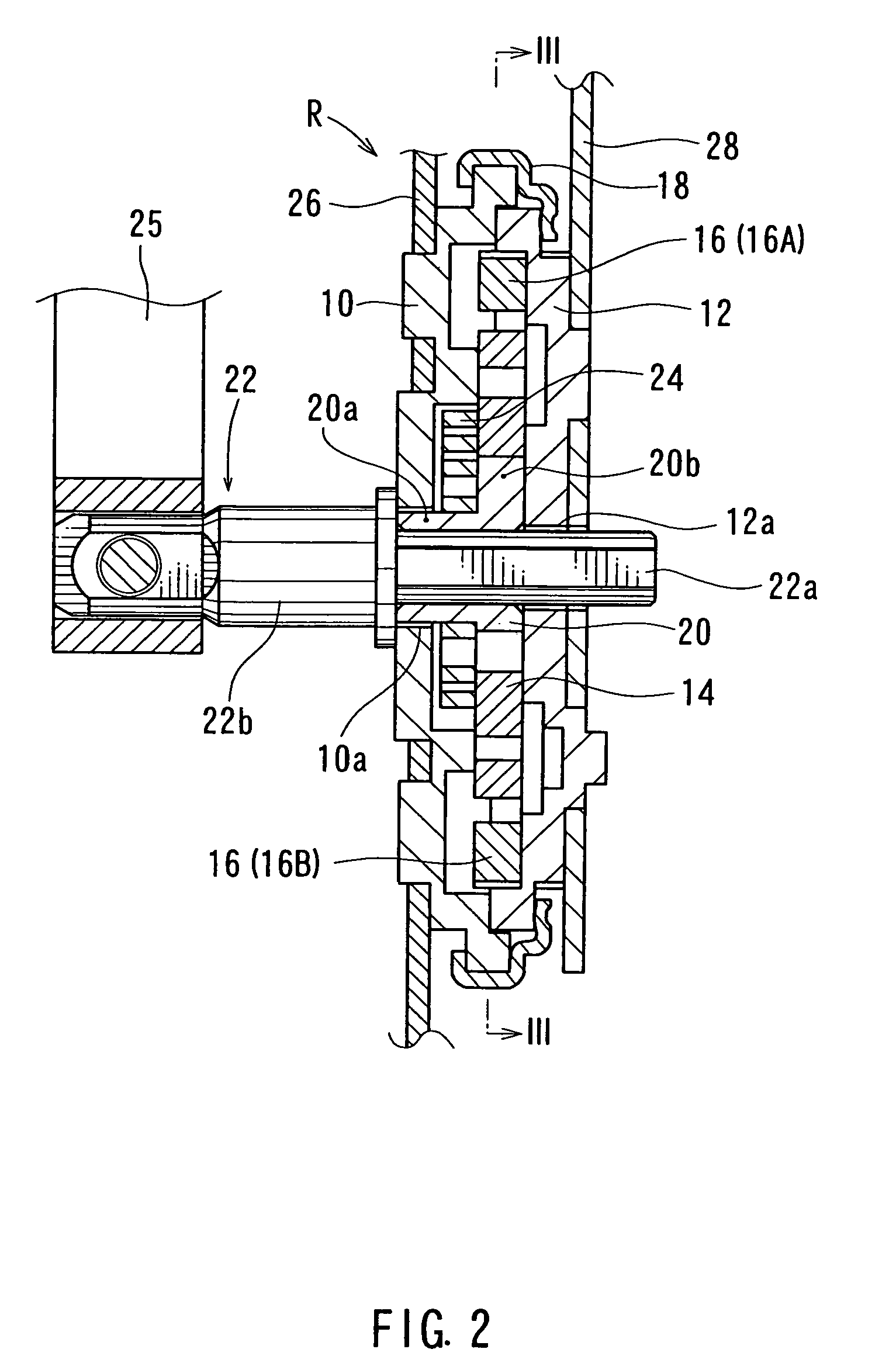
[0027]FIG. 1 is a partially omitted side view of a vehicle seat. FIG. 2 is an enlarged cross-sectional view taken along line II—II in FIG. 1. FIGS. 3–7 are plan views of FIG. 2 viewed along line III—III. As shown in FIG. 1, a rear end of a seat cushion C of a seat is connected to a lower end of a seat back B via a reclining mechanism R. The reclining mechanism R can be unlocked by operating an operation lever 25 so that the seat back B can be tilted back and forth around an operating shaft 22.
[0028]As shown in FIGS. 2 to 3, the reclining mechanism R includes an outer shell that is constructed from a disk-shaped stationary housing 10 and a disk-shaped rotational housing 12. The housings 10 and 12 are oppositely coupled to each other and are relatively rotatably connected by clamping a clip ring 18 that is circumferentially attached thereto (FI...
second embodiment
[0048]Next, the second embodiment will be described with reference to FIG. 8.
[0049]FIG. 8 is a plan view corresponding to FIG. 3 and illustrates a reclining mechanism according to the second embodiment. As will be apparent from this drawing, in the second embodiment, the present invention is applied to a reclining mechanism R that includes a rotating-type operating cam and three slide pawls.
[0050]In FIG. 8, the circular plate-shaped operating cam 114 is positioned in the stationary housing 10 so as to rotate around an axis of an operating shaft 122. Also, the three slide pawls 116 (116A, 116B, 116C) are positioned in pawl guide grooves of the stationary housing 10 so as to radially slide without circumferentially moving. Each of cam portions 114c, 114d and 114e formed in an outer circumferential surface of the operating cam 114 are positioned so as to contact or to be contactable with contact portions 116b of each of the slide pawls 116. The operating cam 114 is rotatably supported ...
PUM
 Abstract
Description
Claims
Application Information
 - R&D
- Intellectual Property
- Life Sciences
- Materials
- Tech Scout
- Unparalleled Data Quality
- Higher Quality Content
- 60% Fewer Hallucinations
Browse by: Latest US Patents, China's latest patents, Technical Efficacy Thesaurus, Application Domain, Technology Topic, Popular Technical Reports.
© 2025 PatSnap. All rights reserved.Legal|Privacy policy|Modern Slavery Act Transparency Statement|Sitemap|About US| Contact US: help@patsnap.com


