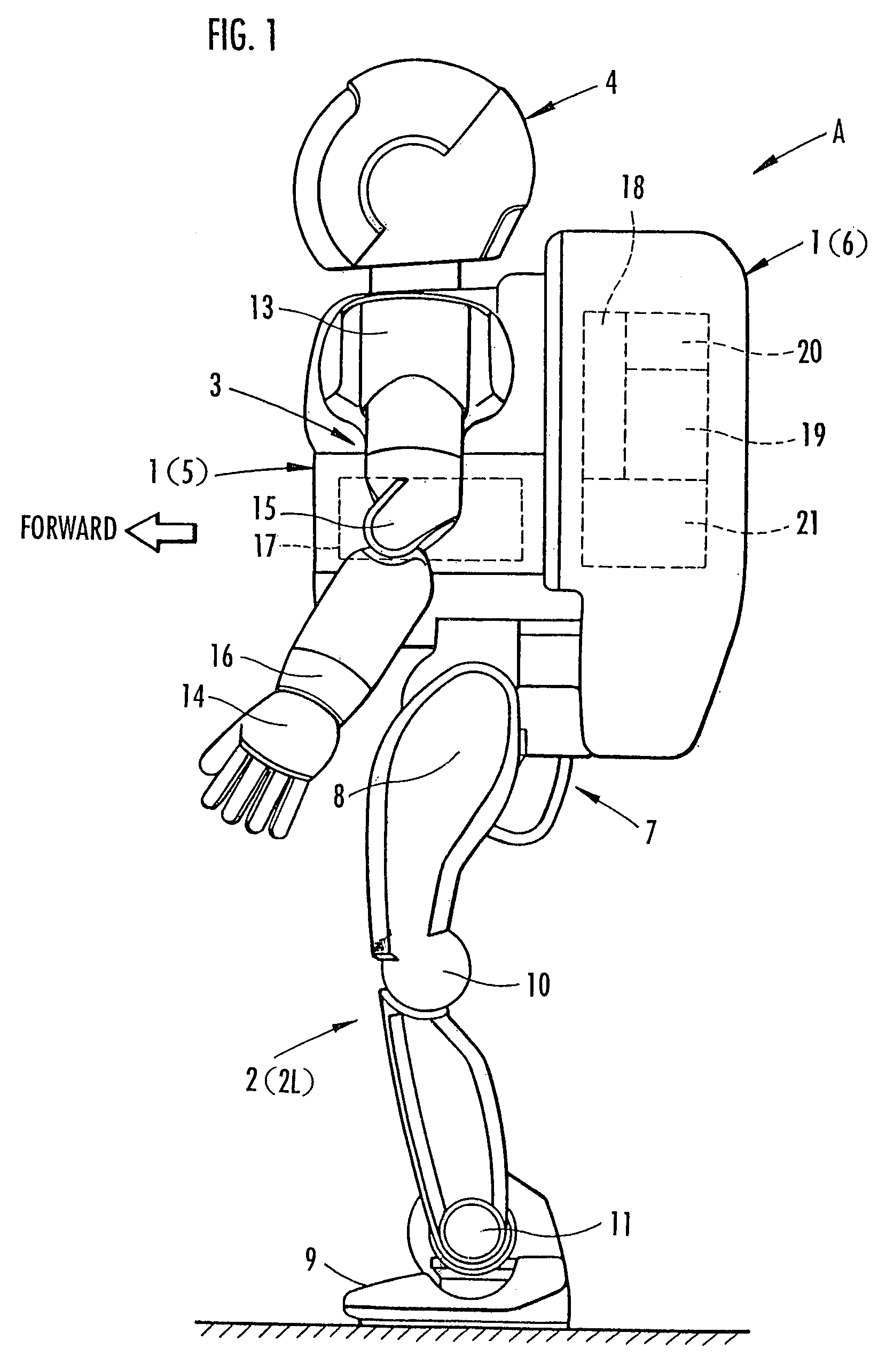
Remote control device of bipedal mobile robot

a mobile robot and remote control technology, applied in the direction of electric programme control, program control, instruments, etc., can solve the problems of difficult to make the robot reach the desired place, difficult to operate such a manipulator lever, and difficult to delicately adjust the manipulator amount, so as to improve the operability of moving the robot, and achieve the effect of easy and selective operation

Active Publication Date: 2007-05-22
HONDA MOTOR CO LTD
View PDF9 Cites 7 Cited by
  • Summary
  • Abstract
  • Description
  • Claims
  • Application Information

AI Technical Summary

Benefits of technology

[0008]As just described, in the first embodiment of the present invention, the moving amount of the bipedal mobile robot toward the desired direction can be set according to the number of operations of the manipulator lever in the stopped state of the bipedal mobile robot, so that this setting may easily be performed. Consequently, the operation for moving the robot in the desired direction to the desired position may easily and surely be performed, so that the movement of the robot to the desired position may surely be performed by a simple operation. Further, the manipulation completing conditions include, for example, whether or not a confirmation switch provided beforehand in the remote control device is operated, or whether or not the manipulator lever is maintained in the non-manipulation state for more than a predetermined fixed period of time, etc.
[0032]According to this attempt, the movement of the bipedal mobile robot by a relatively small moving amount toward a desired direction and the movement by a relatively large moving amount toward a desired direction may selectively be carried out using one remote control device, thereby enabling to improve operability for moving the robot by the remote control device. Furthermore, a scale of the setting value of the moving amount given by the moving amount setting means is arranged to correspond to and vary depending on each movement mode, so that an operation pattern of manipulator lever does not need to vary from one movement mode to the other movement mode and the movement of the robot in two types of movement modes may easily and selectively be carried out.

Problems solved by technology

However, in such a remote control device, when an attempt is made to move the robot to a desired position, the manipulator lever has to be operated by a manipulation amount corresponding to a moving amount from a current position to the desired position, but this manipulating amount is difficult to delicately adjust.
Accordingly, for example, it is difficult to operate such a manipulator lever so that the robot is moved by a relatively minute amount (such a moving amount as a movement can be made by one step) from one place to another place and stopped.
Additionally, even when a place to be reached last is known, the manipulation amount of the manipulator lever is difficult to accurately adjust while moving the robot toward the place, and as a result, it is difficult to make the robot reach the desired place.

Method used


Image

  • Remote control device of bipedal mobile robot
  • Remote control device of bipedal mobile robot
  • Remote control device of bipedal mobile robot

Examples


fourth embodiment

[0059]Referring to the block diagram of FIG. 3, the manipulator 23 is provided with a manipulation signal generating circuit 33 for generating a signal in response to respective operation states of each of the aforementioned manipulator lever 26, the confirmation switch 27, the cancellation switch 28, the opened-legs-stop ON / OFF switch 29, and the movement mode selecting switch 32, an arithmetic processing circuit 34 in which the manipulation signal is input, driving circuits 35, 36 for driving the LED lamps 31 and the liquid crystal display 30, respectively, and a communication processing circuit 37 for taking charge of transmitting / receiving signal data between the arithmetic processing circuit 34 and the communication system 25, in the interior portion thereof. Further, a parenthesized reference numeral (39) regarding to the manipulator levers is a reference numeral with regard to a description of a fourth embodiment to be described later.

[0060]In this situation, regarding each m...

first embodiment

[0115]In this STEP 35, according to the forward / backward time variable TX, the right / left time variable TY, and the turning time variable TTHZ, the arithmetic processing circuit 34 sets the moving amount in the forward / backward direction, the moving amount in the right / left direction, and the moving amount (rotating amount) in the turning direction of the robot A, respectively, based on the predetermined data table for each variable. At this position, like the first embodiment, the above data table is individually provided for each type of the movement modes of the robot A (the minor movement mode or the major movement mode) selected by the movement mode selecting switch 32, resulting in using the data table depending on respective movement modes. In this situation, the moving amount in each direction of the robot A set according to the data table for the minor movement mode is a relatively small moving amount which may move the robot A by alternately performing the lifting / landing ...

second embodiment

[0134]The processing of the arithmetic processing circuit 34 as has been described allows the operator to set the moving amount of the robot A depending on the manipulation amount of the sliding control 38 by operating the sliding control 38 and the manipulator lever 26 in the corresponding direction in turn for each desired direction of the robot A. Further, in the present embodiment, the setting value for the moving amount in each direction will be proportional to the manipulation amount of the sliding control 38, but do not need to satisfy this proportionality, and may be set in such a manner that basically, as the manipulation amount of the sliding control 38 increases, the setting value for the moving amount in each direction increases. In this situation, the setting value for the moving amount with respect to the manipulation amount of the sliding control 38 may also be set according to the data table in each movement mode as in the first or the

[0135]In addition, although a de...


PUM


Abstract

When an operator attempts to move a robot from a current position to a desired position, she / he operates a manipulator lever (26) corresponding to a desired direction of a manipulator (23) of a remote control device (22), for example, a number of times corresponding to a predetermined moving amount in the moving direction. At this point, the moving amount for each moving direction depending on this number of operations is set, and a leg of the robot is actuated according to a setting value of the moving amount for each moving direction to move the robot. The moving amount that can be set by the operation of the manipulator lever (26) has a relatively small moving amount that the robot may be moved by performing a lifting / landing action once for each of the legs of the robot, and a relatively large moving amount requiring multiple walking steps of the lifting / landing action for each leg of the robot.

Description

TECHNICAL FIELD[0001]The present invention relates to a remote control device for a bipedal mobile robot.BACKGROUND ART[0002]In recent years, a bipedal mobile robot, which has been planned to be in a practical use by the present applicants and the like, moves by an action for making two legs to alternately lift and land like a human. Further, in the present specification, “movement” of the bipedal mobile robot includes a movement from one place to another place, as well as such an action as turning almost in the same place to change orientation of the robot. In this turning action, a moving direction of the robot means a turning direction such as a clockwise direction and a counterclockwise direction. Additionally, “a stopped state” of the bipedal mobile robot is a state that the movement of the robot is not performed, so that a state with the two legs stopped as well as such a state as the robot is marching in the same place without changing orientation are included.[0003]The prese...

Claims


Application Information

Patent Timeline
Patent Type & Authority Patents(United States)
IPC IPC(8): G06F19/00B25J13/02B25J13/06B62D57/032
CPCB25J13/02B25J13/06B62D57/032B25J5/00
Inventor SANO, SHIGEO
Owner HONDA MOTOR CO LTD
Why Eureka
Try Eureka