
Locking storage systems for fishing rods

a storage system and fishing rod technology, applied in the field of fishing rods, can solve the problems of theft of fishing rods, cumbersome storage, and often unattended, and achieve the effects of reducing the risk of th

Inactive Publication Date: 2007-05-22
KUJAWA JOHN
View PDF41 Cites 56 Cited by
  • Summary
  • Abstract
  • Description
  • Claims
  • Application Information

AI Technical Summary

Problems solved by technology

Because these rods are somewhat cumbersome they are often left unattended, for example in the cockpit of a vessel.
Not surprisingly, it is not at all uncommon for these rods to be stolen off a boat while the vessel is docked overnight at a marina, left unattended at a fuel dock, or even when stopped at a traffic light while the boat is being pulled.
Similarly, rods being transported in a vehicle or stored in a garage are also targets of thieves.
In short, any time fishing rods are left unattended and unsecured the potential for theft exists.
While several locking mechanisms for fishing rods exist, these either lock only the actual fishing rod (and not the reel) or require a cumbersome box to encase all or part of the rod / reel combination.
Moreover, many of the existing designs do not allow for quick, unencumbered access to fishing gear when locking attributes are not required, and do not offer effective duality of use for storing related boating or fishing items such as gaffs, boat brushes, or boat hooks.
However, this holder offers no security against theft.
Simple ‘rod type’ locking mechanisms, such as the truck bumper-mounted unit described in U.S. Pat. No. 5,435,473 provide a simple solution to the prevention of theft, however designs requiring full removal of the locking rod preclude installation on many of the available mounting surfaces of a boat (such as under a gunwale with an overhang, or on the inner surface of a narrow transom).
Moreover, such a design exposes a significant portion of the locking rod, inviting would-be thieves to simply cut the rod and remove the fishing rod and reel combinations.
Finally, such locking devices are limited in their ability to lock reels other than spinning reels (e.g. conventional reels or fly reels) because these types of reels do not have a reel stem which sets the main body of the reel off from the fishing rod.
Enclosed designs, such as those described in U.S. Pat. Nos. 6,499,248 B2 and 4,572,416 are typically intended for automobile roof top transport of rods and are not suitable for boats because they require an inordinate amount of space.
Perhaps more importantly, the unit obviously cannot be used to hold rods that need to be quickly and easily accessed, such as while fishing.
In addition, this design is limited with respect to the breadth of reel sizes that it can accommodate.
However, smaller rod / reel combinations may not be enclosed snugly enough to prevent their disassembly and subsequent removal from the rack.
Similarly, such limitations deem these designs ill-suited for storing related boating accessories such as gaffs, boat brushes, and boat hooks.
Moreover, this design requires more installation space as there are (2) independent units, which must installed.
Finally, the specific design cited requires the use of 2 separate padlocks to secure the rods, reducing convenience.
However such designs obviously provide storage for only a single fishing rod.
Storing multiple fishing rods would obviously require multiple padlocks, multiple mountings, etc, thus greatly increasing complexity of both installation and use.

Method used


Image

  • Locking storage systems for fishing rods
  • Locking storage systems for fishing rods
  • Locking storage systems for fishing rods

Examples


second embodiment

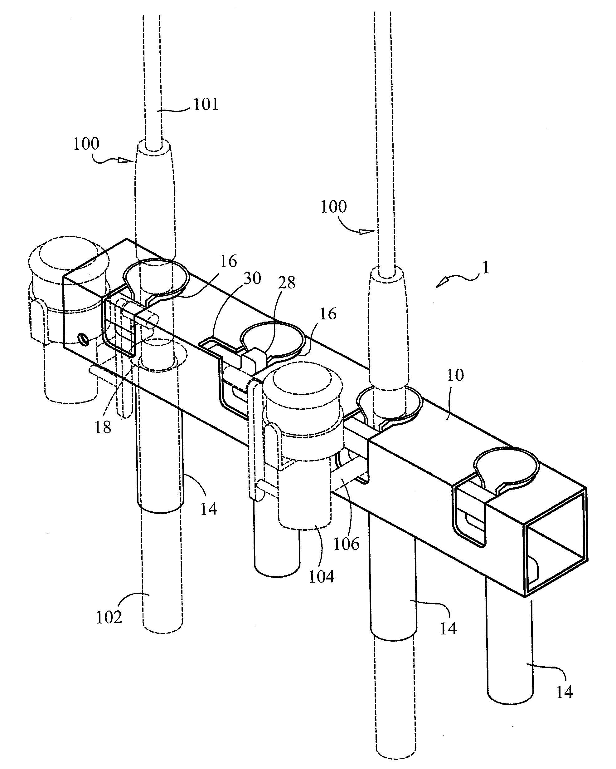
[0040]Referring briefly to FIGS. 9–11, locking storage system for fishing rods 2 preferably includes a contoured rod base 58 and a sliding lock plate 60. The contoured rod base 58 preferably includes at least two contoured cavities 62 that are each sized to receive a bait-casting, trolling, or other reel 114. Many reels 114 are configured with a reel clamp which can aid in preventing access to mounting hardware once fishing rods are inserted in place. A rod hole 64 is formed through a bottom of the contoured rod base 58 to receive an end 118 of a rod 116. At least two sliding plate retainers 66 extend from a front of the contoured rod base 58. At least two sliding plate retainers 66 are sized to slidably receive the sliding lock plate 60.

[0041]A plate-locking hole 68 is formed through one end of the sliding lock plate 60 and a base lock hole 70 is formed through one end of the contoured rod base 58. The plate-locking hole 68 and the base lock hole 70 are sized to receive the bolt 11...

third embodiment

[0043]Referring briefly to FIGS. 13–14, a locking storage system for fishing rods 3 preferably includes a rod tray 74, a rod support 76 and a swinging lock plate 78. The rod tray 74 includes a base 80 and a peripheral wall 82 extending upward from a perphery of the base 80. A rod support 84 extends upward from the base 80. At least two rod cavities 86 are formed in a top of the rod support 84 to receive the rods 116 of at least two fishing rods 111. One end of the swinging lock plate 78 is pivotally attached to the rod support 84. The other end of the swinging lock plate 78 is captured by a lock plate 88 extending from the peripheral wall 82. A lock hole 89 is formed through the other end of the swinging lock plate 78 and the lock plate 88 to receive a bolt of a padlock (not shown).

[0044]At least two parallel slots 90 are preferably formed in one side of the swinging lock plate 78. At least two rod holes 92 are formed through the peripheral wall 82 to receive at least two fishing ro...


PUM


Abstract

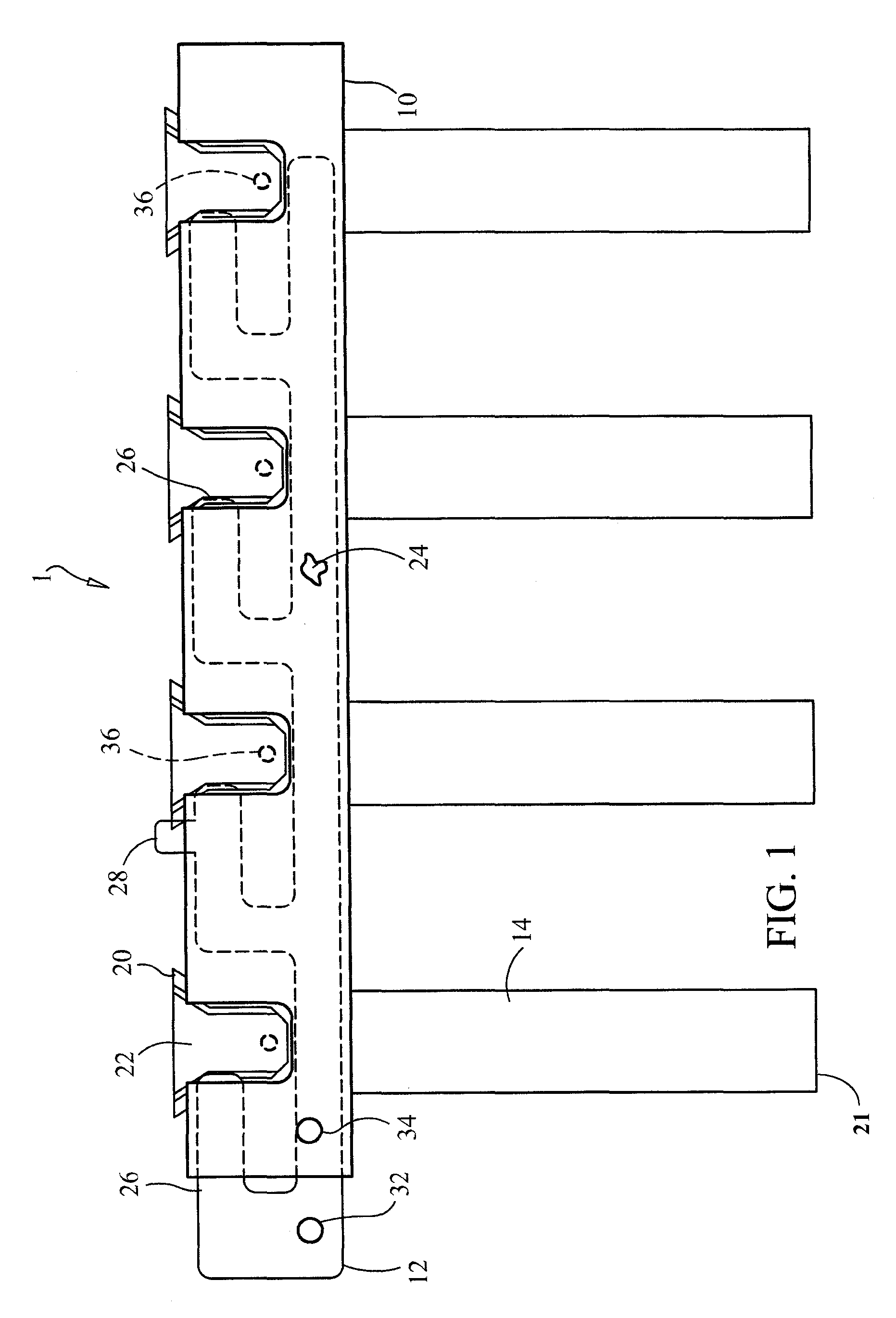
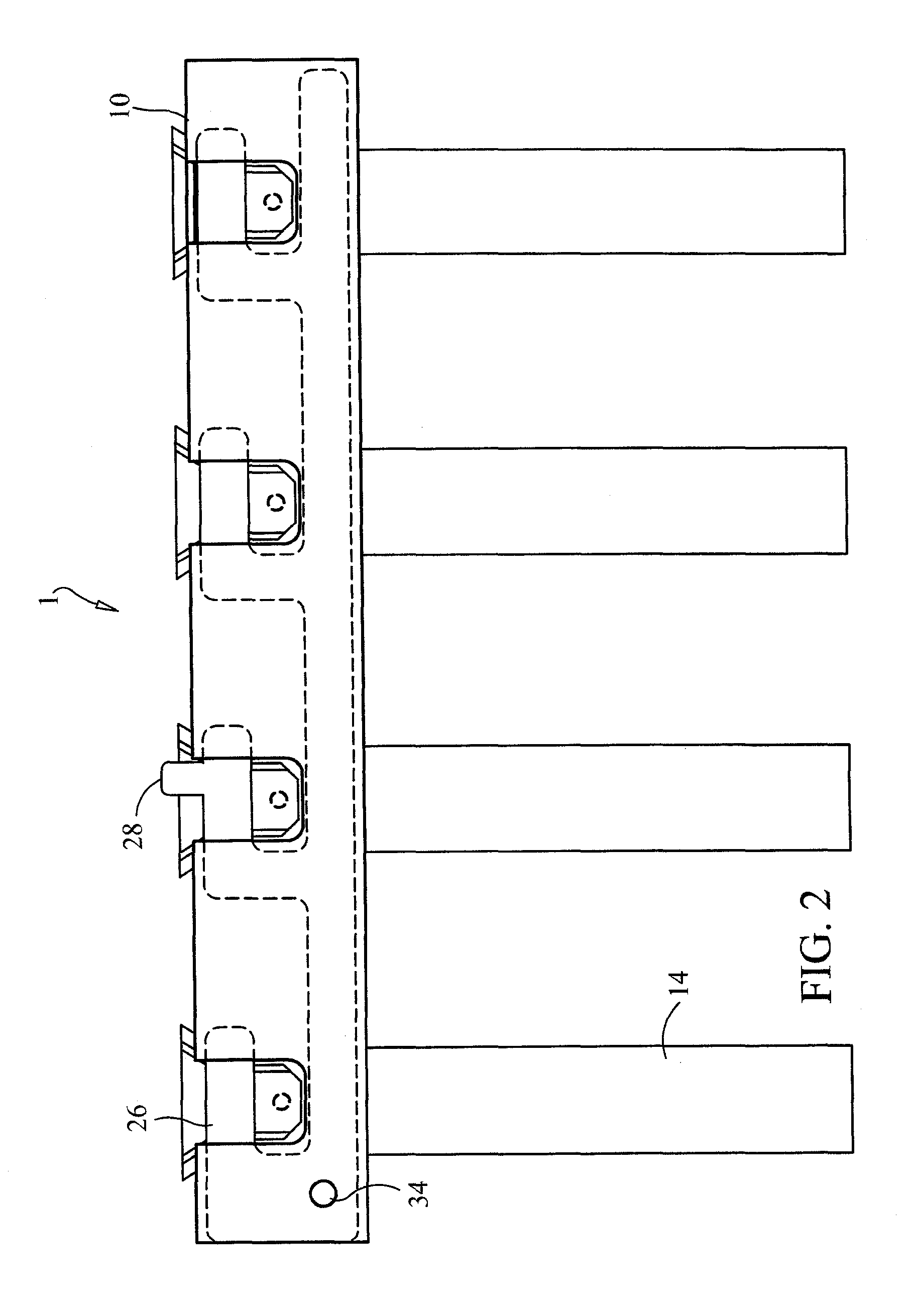
A locking storage system for fishing rods includes a retention base, a sliding lock plate and a plurality of rod collars. A plurality of openings are formed through the retention base. A rod collar is inserted through the openings. The rod collar is sized to receive the end of a fishing rod. The sliding lock plate captures the reel pedestal of a reel of a fishing rod. The sliding lock plate is secured to the retention base with a padlock. A rod retention plate may be used in conjunction with the locking storage system for fishing rods. A second embodiment includes a contoured rod base and a sliding lock plate engaged with the contoured rod base. A third embodiment includes a rod tray, a rod support and a swinging lock plate.

Description

CROSS-REFERENCE TO RELATED APPLICATION[0001]This application claims the benefit of now abandoned U.S. Provisional Patent Application Ser. No. 60 / 618,842, filed Oct. 14, 2004, which is incorporated herein in its entirety.BACKGROUND OF THE INVENTION[0002]1. Field of the Invention[0003]The present invention relates generally to fishing rods and more particularly, to locking storage systems for fishing rods, which allow a plurality of fishing rods to be stored and locked on a vessel or the like, when not in use.[0004]2. Description of the Prior Art[0005]Avid anglers engaging in some types of fishing may utilize 4, 6, or more expensive fishing rods in the course of a fishing day. Because these rods are somewhat cumbersome they are often left unattended, for example in the cockpit of a vessel. Not surprisingly, it is not at all uncommon for these rods to be stolen off a boat while the vessel is docked overnight at a marina, left unattended at a fuel dock, or even when stopped at a traffic...

Claims


Application Information

Patent Timeline
Patent Type & Authority Patents(United States)
IPC IPC(8): A01K97/10
CPCA01K97/08A47B81/005Y10S224/922Y10T70/5009
Inventor KUJAWA, JOHN
Owner KUJAWA JOHN
Learn More