
Holding device and cleaning tool with the holding device

a technology of holding device and cleaning tool, which is applied in the direction of carpet cleaners, screw threaded joints, rod connections, etc., can solve the problems of difficult operation, inability to visually confirm the engaged state from outside, and short handle cleaning tools are not suitable for floor and ceiling cleaning, etc., and achieve the effect of easy attachment to the support member or replacemen

Inactive Publication Date: 2007-05-22
UNI CHARM CORP
View PDF29 Cites 82 Cited by
  • Summary
  • Abstract
  • Description
  • Claims
  • Application Information

AI Technical Summary

Benefits of technology

The present invention provides a holding device for a cleaning wiper that allows for easy and stable attachment and detachment of a cleaning wiper. The holding device includes a telescopic handle with a front and rear end, and a support member attached to the front end for attachment of the cleaning wiper. The telescopic handle has a front-side separate shaft and a rear-side separate shaft, which can be extended and retracted. The front-side separate shaft has an elastic arm and an engaging projection, while the rear-side separate shaft has a through-hole passing through its cylinder wall. The engaging projection of the front-side separate shaft can fit into the through-hole of the rear-side separate shaft to securely hold the telescopic handle in its extended position. The holding device is easy to manufacture, assemble, and use.

Problems solved by technology

However, such a short handle cleaning tool is not suitable for floor and ceiling cleaning, although it is suitable for cleaning within reach.
However, since the length locking means are both hidden by the cylinders, visual confirmation of the engaged state from outside is impossible.
Therefore, after the small cylinder is pulled out of the medium cylinder, completion of the engagement need be confirmed such as by applying a retracting force between them, and similar confirmation is also required between the medium cylinder and the large cylinder, making the operation complicated.
When the handle is to be retracted, on the other hand, the engagement of the engaging projection in the engaging groove need be released at each length locking means by applying a strong retracting force between the cylinders, so that the strong retracting force need be applied twice for releasing the individual engagements at the two length locking means, making the handle retracting operation complicated, too.
In addition, when a strong retracting force acts on the extended handle during cleaning operation, the engagement at the length locking means may possibly be released, resulting in unexpected retraction of the handle.
Particularly if the engaging projection and the engaging groove are worn due to long time use, the engagement at the length locking means becomes unstable, so that the engagement tends to be unexpectedly released during cleaning operation.

Method used


Image

  • Holding device and cleaning tool with the holding device
  • Holding device and cleaning tool with the holding device
  • Holding device and cleaning tool with the holding device

Examples


Embodiment Construction

[0051]The present invention will be discussed hereinafter in detail in terms of the preferred embodiment according to the present invention with reference to the accompanying drawings. In the following description, numerous specific details are set forth in order to provide a thorough understanding of the present invention. It will be obvious, however, to those skilled in the art that the present invention may be practiced without these specific details. In other instance, well-known structures are not shown in detail in order to avoid unnecessary obscurity of the present invention.

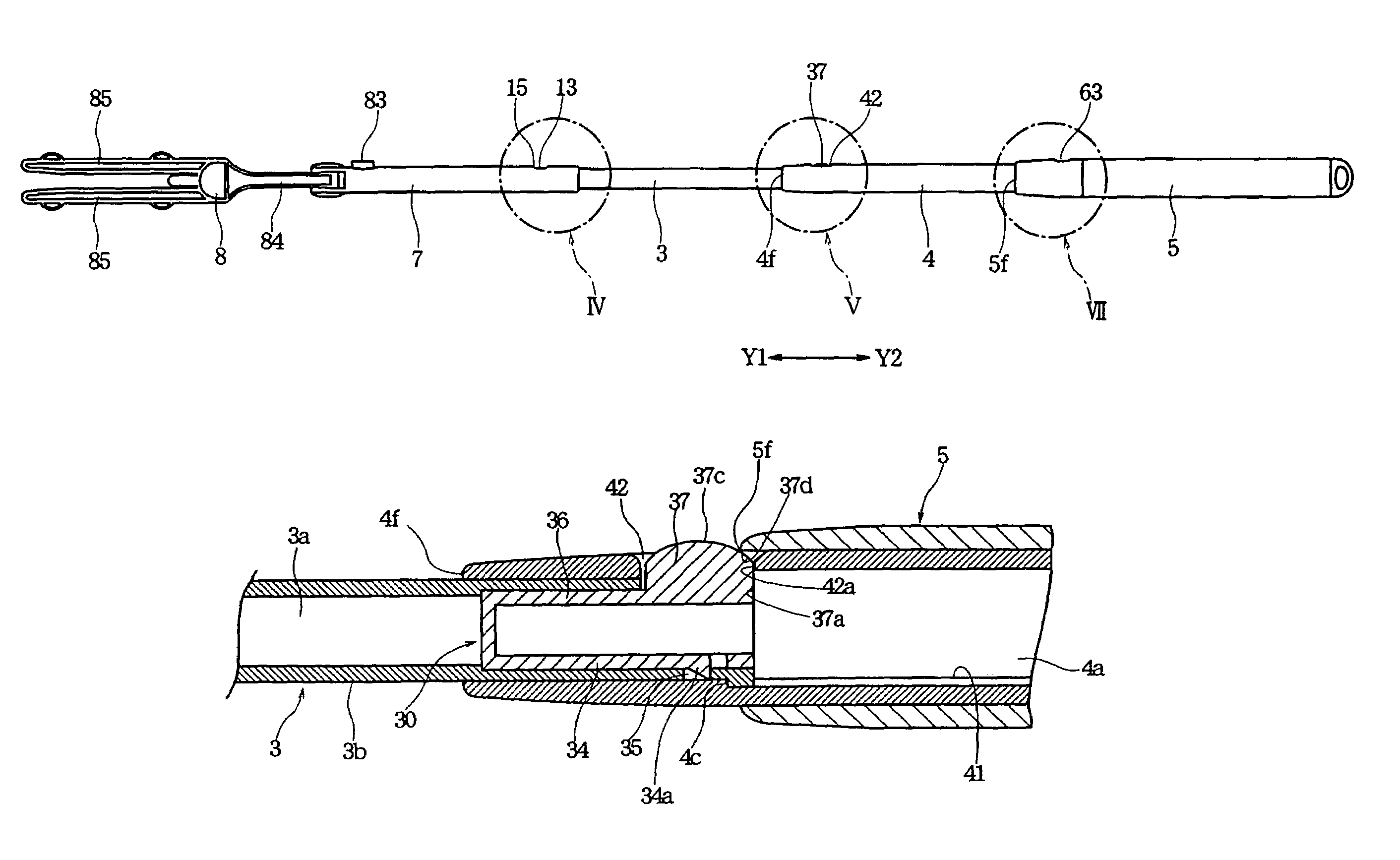
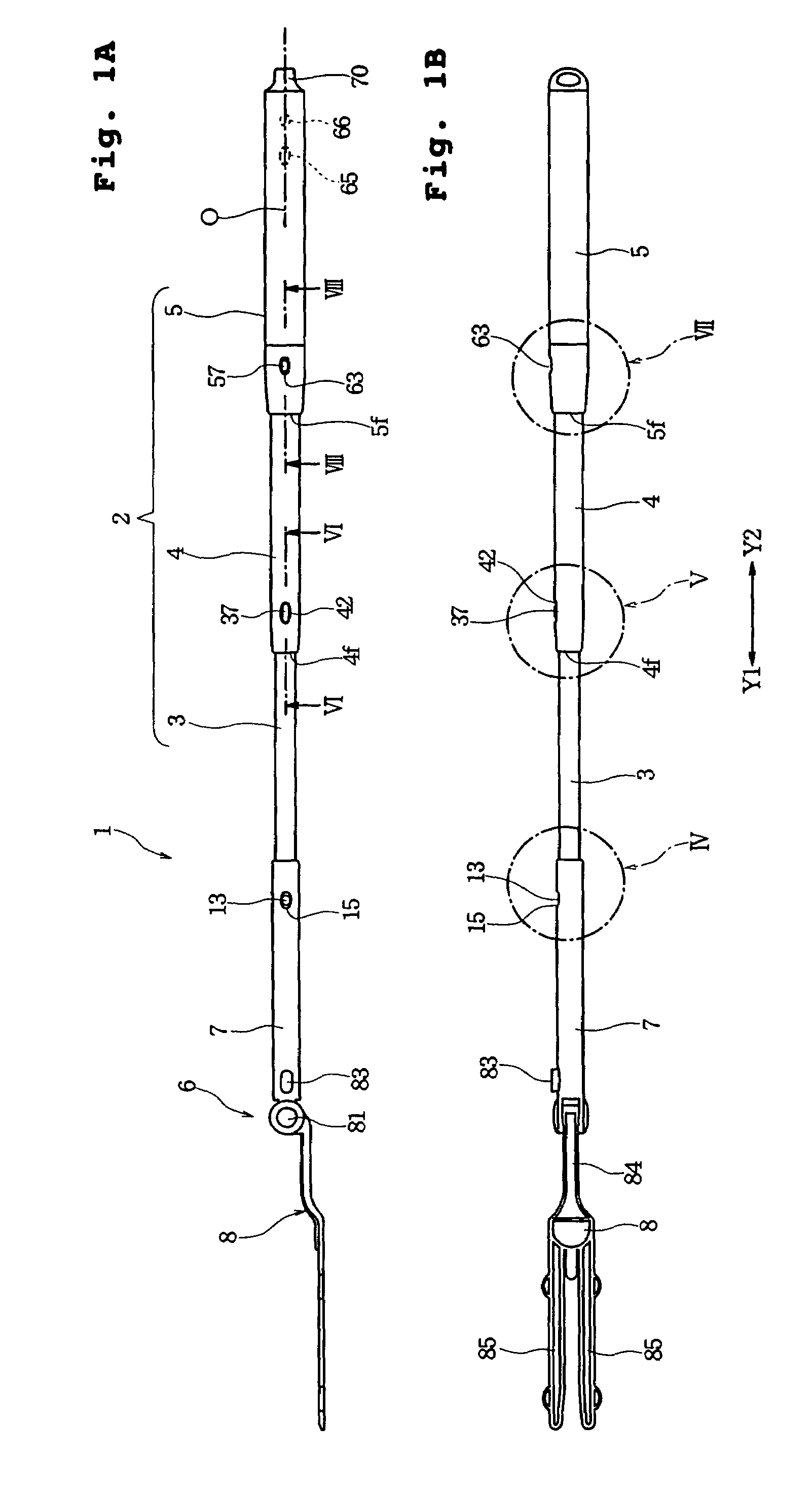
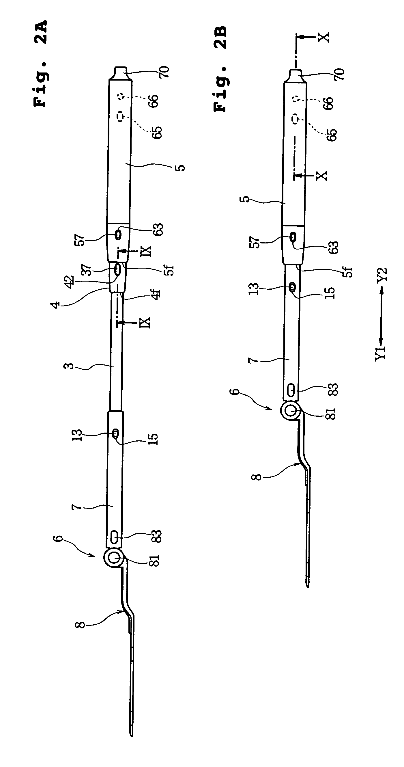
[0052]FIG. 1A is a side view and FIG. 1B is a bottom plan view, in which a holding device according to one embodiment of the present invention is illustrated with its telescopic handle fully extended; FIG. 2A is a side view showing the telescopic handle in a partly retracted position and FIG. 2B is a side view showing the telescopic handle in a fully retracted position; and FIG. 3 is a perspective view sh...


PUM


Abstract

Disclosed is a holding device including: a telescopic handle having axially opposed front and rear ends and constructed of at least two separate shafts, of which a front-side separate shaft axially fits within a rear-side separate shaft being a hollow cylinder; and a support member provided at the front end of the telescopic handle for attachment of a cleaning wiper. The front-side separate shaft has an axially extending elastic arm and an engaging projection provided at a leading end of the elastic arm, while the rear-side separate shaft has a through-hole passing through a cylinder wall thereof, in which the engaging projection engages when the front-side separate shaft projects from the rear-side separate shaft by a predetermined length. Pressing the engaging projection, which engages in the through-hole, from outside the rear-side separate shaft permits release of the engaging projection from the through-hole.

Description

CROSS-REFERENCE TO RELATED APPLICATIONS[0001]This application is a Continuation of International Patent Application Serial No. PCT / JP2003 / 09159 filed on Jul. 18, 2003, which claims priority to Japanese Patent Application No. 2002-212756 filed on Jul. 22, 2002, both of which are incorporated by reference herein in their entireties.BACKGROUND OF THE INVENTION[0002]1. Field of the Invention[0003]The present invention relates to a device for holding a disposable or reusable cleaning wiper and a cleaning tool constructed of the holding device and the cleaning wiper.[0004]2. Description of the Related Art[0005]Japanese Patent Publication No. 2977477 discloses a cleaning tool in which a head is provided at a front end of a short handle that can be held with one hand and a disposable cleaning cloth comprising nonwoven fabric is attached to the head. However, such a short handle cleaning tool is not suitable for floor and ceiling cleaning, although it is suitable for cleaning within reach.[0...

Claims


Application Information

Patent Timeline
Patent Type & Authority Patents(United States)
IPC IPC(8): B25G1/04A47L13/20A47L13/24A47L13/38A47L13/42B25G3/18F16B7/10F16B7/12
CPCA47L13/20A47L13/24A47L13/38A47L13/42B25G3/18B25G1/04Y10T403/32467F16B7/105Y10T16/473
Inventor TSUCHIYA, AKEMITANAKA, YOSHINORIFUJIWARA, MASATOSHI
Owner UNI CHARM CORP
Learn More