
Suture loop anchor

a technology of suture loop and thread, which is applied in the field of suture anchors, can solve the problems of disadvantageous movement or twisting of the suture thread, unwanted tangling and knotting, and difficulty or delay in threading the sutur

Active Publication Date: 2007-05-15
DEPUY SYNTHES PROD INC
View PDF19 Cites 281 Cited by
  • Summary
  • Abstract
  • Description
  • Claims
  • Application Information

AI Technical Summary

Benefits of technology

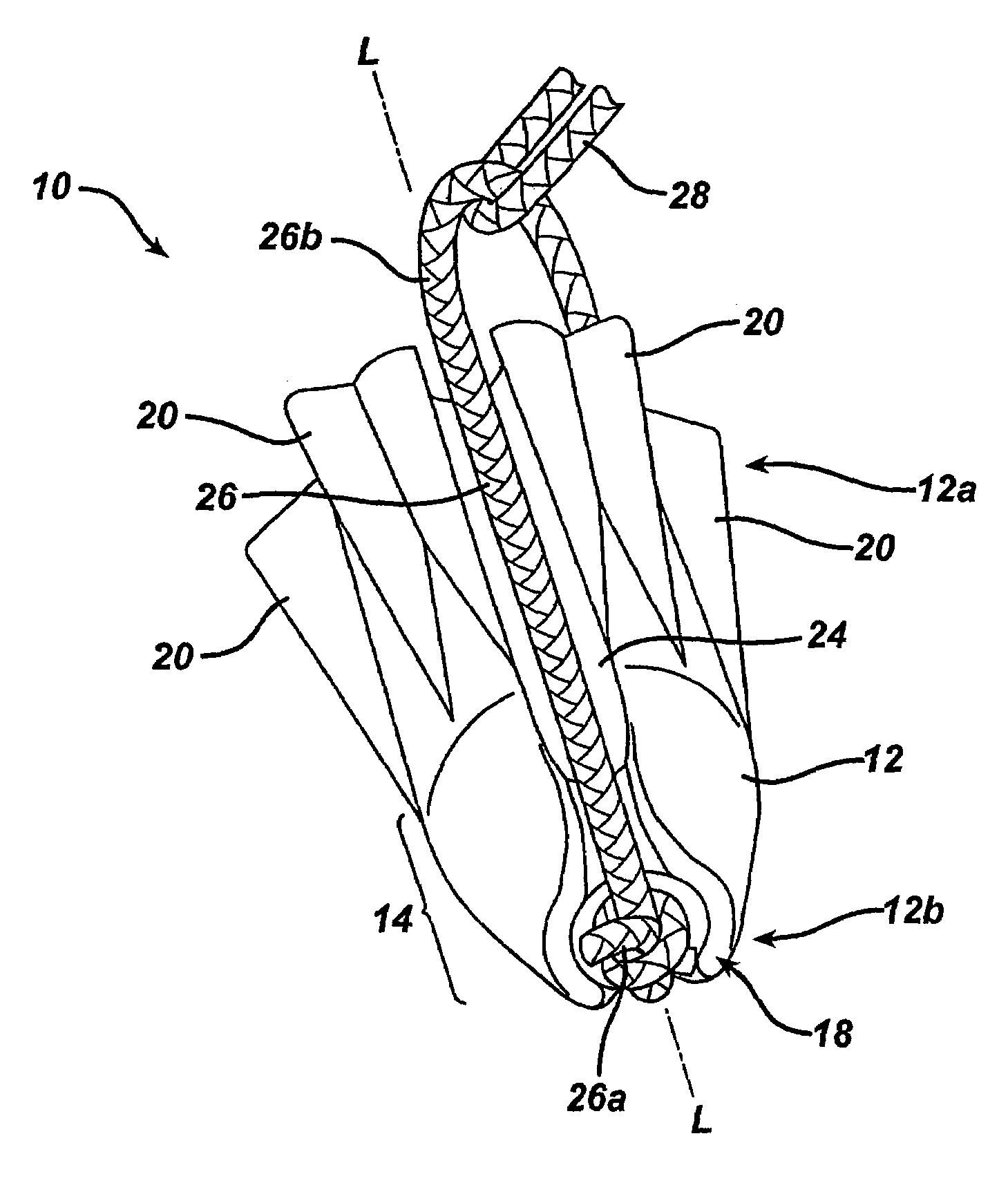
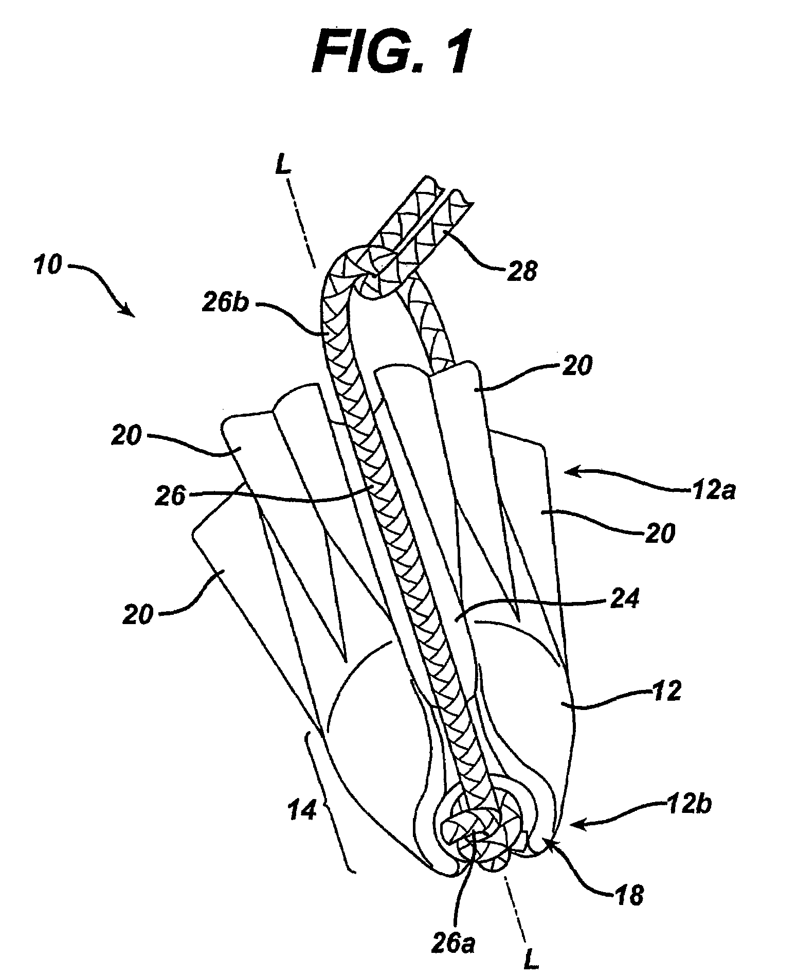
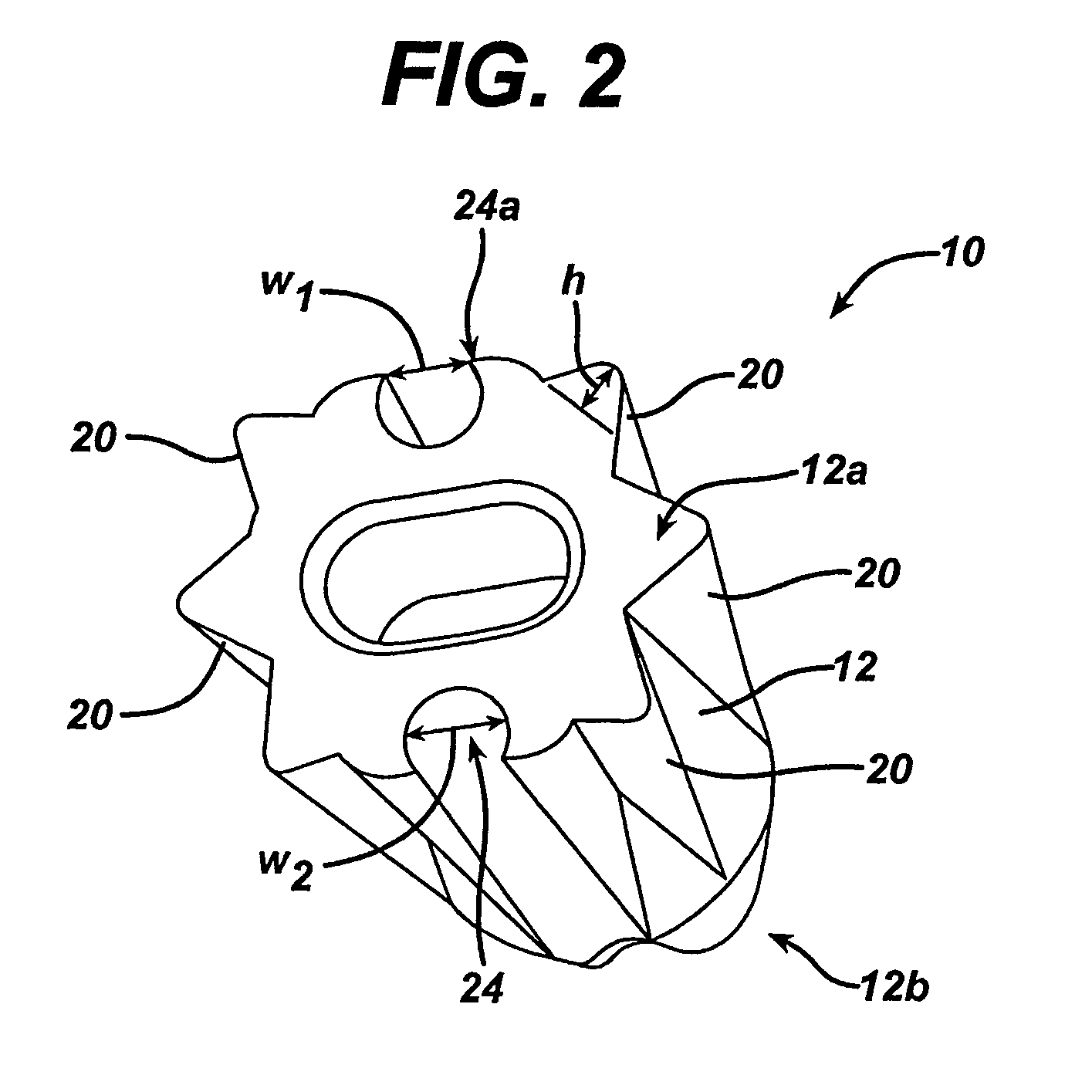
The present invention provides a suture anchor system for anchoring tissue to bone. The system includes an elongate body with longitudinally extending bone-engaging surface features and a continuous suture-receiving channel or recess extending distally from the proximal end of the body around the distal end. The suture-receiving channel is adapted to seat a suture therein, and the system also includes a first loop of suture thread freely-slidably disposed around the elongate body within the at least one suture-receiving channel. The system can be used to anchor a suture in bone by forming a bone cavity within a bony structure, passing the operative suture through the proximal portion of the suture loop, and implanting the suture anchor in the bone cavity such that the operative suture extends from the cavity and is freely slidable with respect to the suture loop.

Problems solved by technology

While many conventional suture anchors are successful in anchoring tissue to bone, they suffer from some disadvantages as well.
For example, many conventional suture anchors provide small passageways through which the suture must be threaded, causing difficulties or delays in threading the suture.
Moreover, attachment of the suture thread to the anchor, typically at the distal end of the anchor, can result in disadvantageous movement or twisting of the suture thread.
Where two free ends of suture thread are required or desired, unwanted tangling and knotting may occur when two suture ends exit the anchor through a single hole in the anchor body or on the same side of the anchor body.
Other disadvantages can result where the anchor is a screw-type anchor.
For example, the suture thread can be abraded or otherwise damaged when the anchor is threaded into bone.

Method used


Image

  • Suture loop anchor
  • Suture loop anchor
  • Suture loop anchor

Examples


Embodiment Construction

[0014]The present invention generally provides a suture anchor that includes a body having proximal and distal ends with at least one suture-receiving channel that extends distally from the proximal end of the body. The suture-receiving channel can include a cavity formed in a distal-most end of the body, or it can terminate at a transversely-extending bore formed through the body. The suture anchor can also include a suture loop that is positioned within the suture-receiving channel and cavity or bore, and that includes a proximal portion that extends proximal of the proximal end of the body. In use, an operative suture can be passed through the proximal portion of the suture loop to attach the operative suture to the anchor. This is particularly advantageous in that the operative loop is freely-slidable with respect to the suture loop, thus facilitating attachment and / or positioning of the operative loop with respect to tissue being anchored to the bone containing the anchor. The ...


PUM


Abstract

A suture anchor is provided having a body with at least one suture-receiving channel that extends distally from a proximal end of the body. The suture-receiving channel can include a cavity formed in a distal-most end of the body, or it can terminate at a transversely-extending bore formed through the body. The suture anchor can also include a suture loop that is positioned within the suture-receiving channel and cavity or bore, and that includes a proximal portion that extends proximal of the proximal end of the body.

Description

FIELD OF THE INVENTION[0001]The present invention relates to suture anchors, and in particular to a suture anchor having a suture loop for receiving an operative suture.BACKGROUND OF THE INVENTION[0002]Soft tissues, such as ligaments, tendons and muscles, are attached to a large portion of the human skeleton. In particular, many ligaments and tendons are attached to the bones which form joints, such as shoulder and knee joints. A variety of injuries and conditions require attachment or reattachment of a soft tissue to bone. For example, when otherwise healthy tissue has been torn away from a bone, surgery is often required to reattach the tissue to the bone to allow healing and a natural reattachment to occur.[0003]A number of devices and methods have been developed to attach soft tissue to bone. These include screws, staples, cement, suture anchors, and sutures alone. Some of the more successful methods involve use of a suture anchor to attach a suture to the bone, and tying the su...

Claims


Application Information

Patent Timeline
Patent Type & Authority Patents(United States)
IPC IPC(8): A61B17/04A61B17/06A61B17/56
CPCA61B17/0401A61B2017/0412A61B2017/0414A61B2017/0427A61B2017/0437A61B2017/0458A61B2017/06042
Inventor REESE, KARL S.
Owner DEPUY SYNTHES PROD INC
Learn More