
Hinge assembly and housing

a technology of hinge and housing, which is applied in the direction of casing/cabinet/drawer details, wing accessories, instruments, etc., can solve the problems of sub-body movement, high cost of manufacture and assembly, and complex structure of hinge, and achieve the effect of simplifying the angle adjustment structur

Inactive Publication Date: 2007-05-15
SAMSUNG ELECTRONICS CO LTD
View PDF36 Cites 38 Cited by
  • Summary
  • Abstract
  • Description
  • Claims
  • Application Information

AI Technical Summary

Benefits of technology

[0012]It is, therefore, an object of the present invention to provide a hinge assembly adapted for use with a housing, the hinge assembly having a simplified angle adjustment structure.
[0013]It is another object of the present invention to provide a hinge assembly in which a spring back phenomenon does not occur when a sub-body angle is adjusted.
[0014]It is further another object of the present invention to provide a hinge assembly for facilitating an angle adjustment of the sub-body.

Problems solved by technology

However, such a hinge device has a problem in that its structure is very complex and manufacture and assembly thereof are very costly.
Furthermore, when the sub-body is maintained at a predetermined angle by a friction force of the disk, the hinge assembly has another problem in that the sub-body can move when the friction force is weak, and alternatively, a high force is required to move the main body when the friction force has been increased to prevent the sub-body from moving.
In addition, the hinge assembly has still another problem in that a spring back phenomenon occurs when the sub-body is rotated due to the friction force of the disk.

Method used


Image

  • Hinge assembly and housing
  • Hinge assembly and housing
  • Hinge assembly and housing

Examples


Embodiment Construction

[0048]The present invention will now be described more fully hereinafter with reference to the accompanying drawings, in which an exemplary embodiment of the present invention is shown. The present invention can, however, be embodied in different forms and should not be construed as being limited to the embodiment set forth herein. Rather, the embodiment is provided so that this disclosure will be thorough and complete, and will fully convey the scope of the invention to those skilled in the art. In the drawings, the thickness of layers and regions have been exaggerated for clarity. Like numbers refer to like elements throughout the specification.

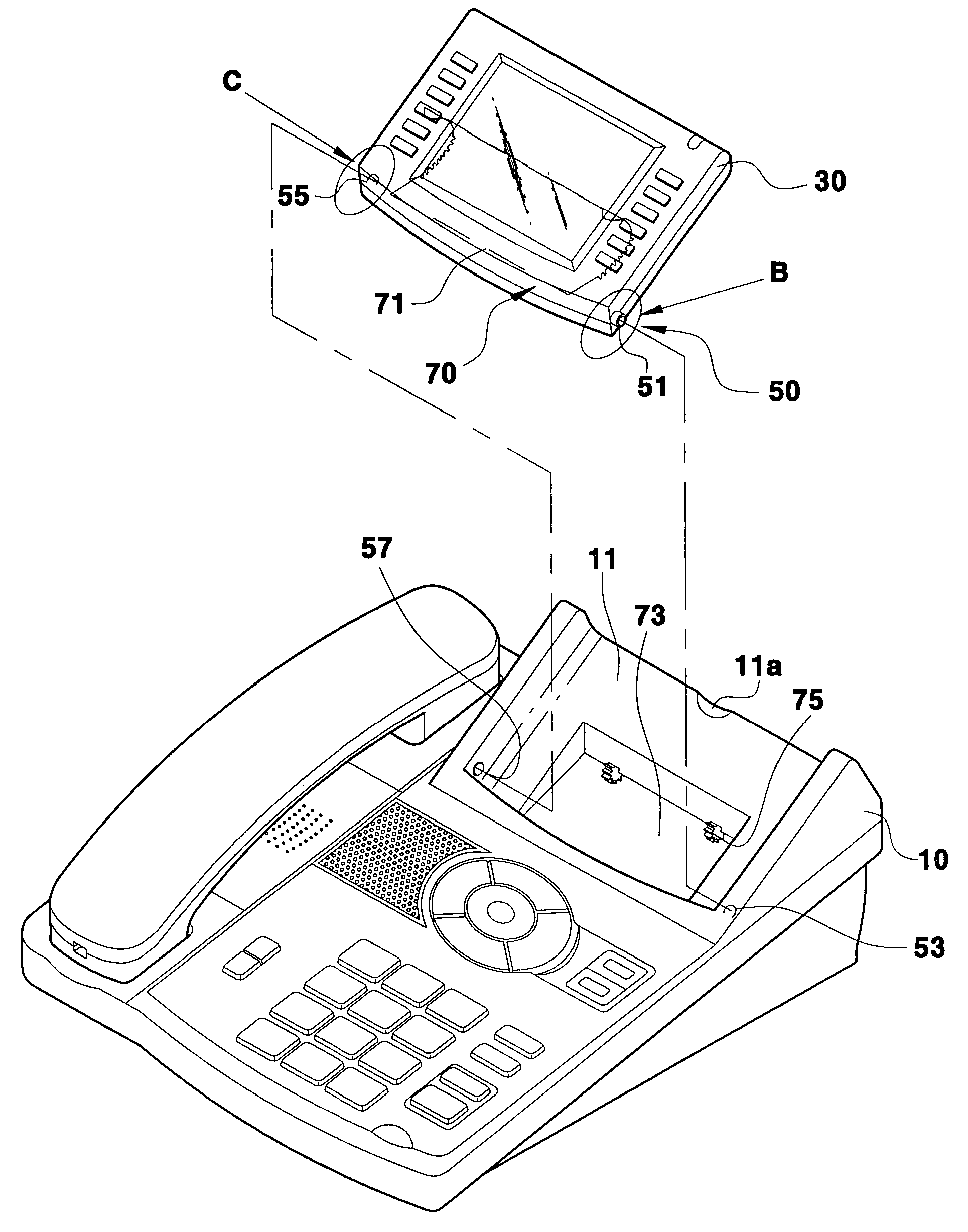
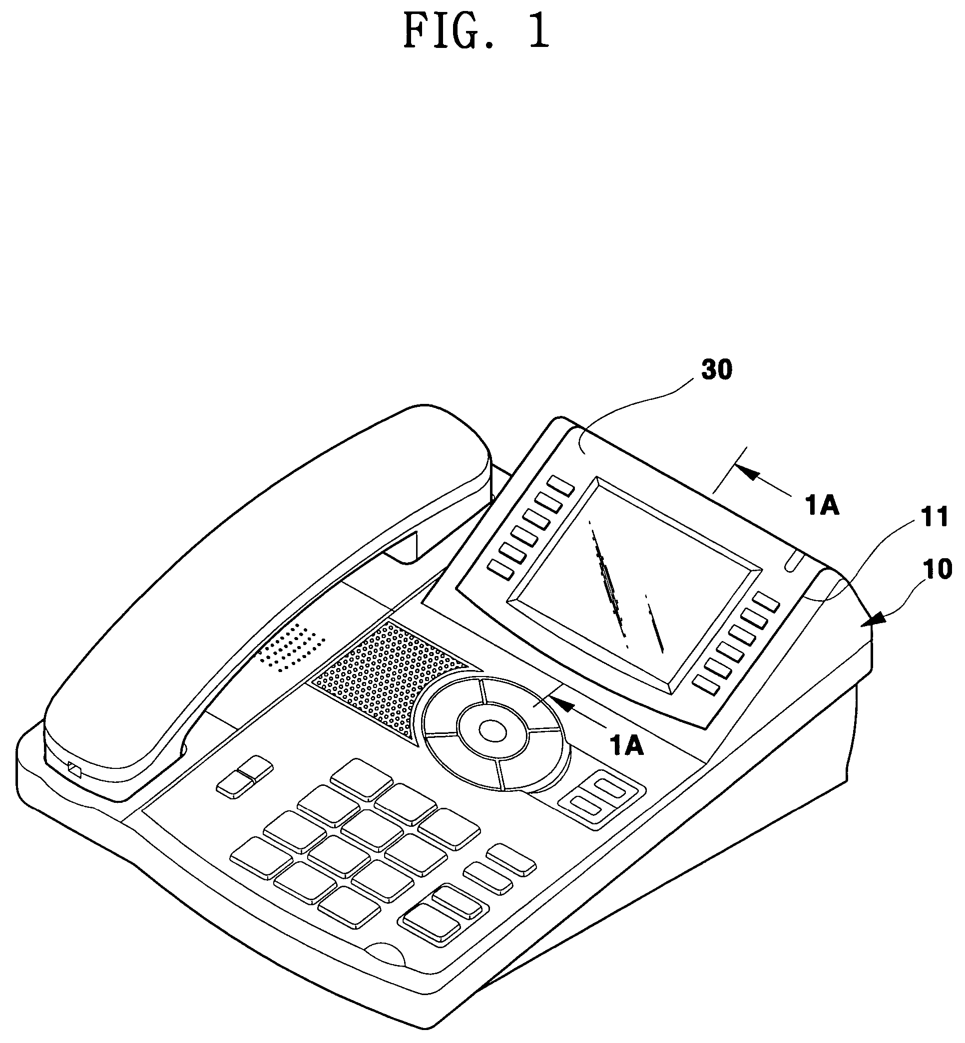
[0049]As shown in FIG. 1, a sub-body 30 is positioned on a main body 10 to be adjustable (where, for example, the main body 10 corresponds to a main body of a telephone, and the sub-body 30 corresponds to an LCD module of the telephone).

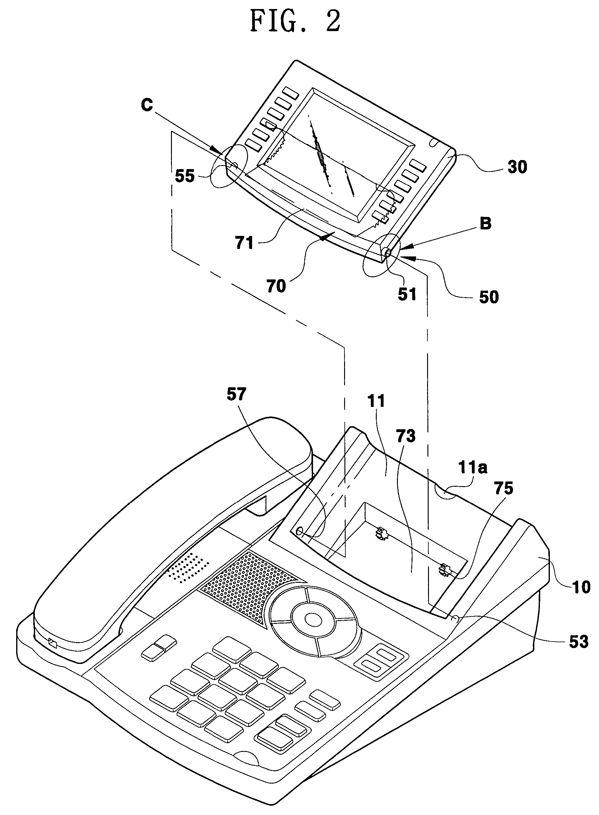
[0050]As shown in FIG. 2, an upper surface of the main body 10 is provided with a sub-body rotational spa...


PUM


Abstract

A hinge assembly adapted for a housing having a main body and a sub-body rotatably positioned on the main body, the hinge assembly including: a first hinge portion adapted to rotatably support both lower sides of the sub-body; and a second hinge portion adapted to rotatably support a rear surface of the sub-body with a surface contact and to maintain a rotated angle of the sub-body. The first hinge portion includes: a hinge protrusion arranged on one side surface of the sub-body; a hinge protrusion inserting-hole arranged on one side surface of a sub-body rotational space and adapted to receive the hinge protrusion; a hinge-hole arranged on the other side surface of the sub-body; a through-hole arranged on the other side surface of a sub-body rotational space to correspond to the hinge-hole; and a hinge locker passing through the through-hole and the hinge-hole. The second hinge portion includes: a curved portion protruding from a bottom surface of the sub-body and having a gear groove arranged on the surface thereof; a window arranged on the sub-body rotational space of the main body and passing through the curved portion; and a pinion rotatably positioned at a predetermined position, the pinion arranged to be rotated together with the sub-body upon the sub-body being rotated in engagement with the gear groove.

Description

CLAIM OF PRIORITY[0001]This application makes reference to, incorporates the same herein, and claims all benefits accruing under 35 U.S.C. § 119 from an application for HINGE ASSEMBLY AND HOUSING earlier filed in the Korean Intellectual Property Office on 13 Oct. 2003 and there duly assigned Serial No. 2003-71197.BACKGROUND OF THE INVENTION[0002]1. Field of the Invention[0003]The present invention relates to a hinge assembly adapted for use with a housing having a sub-body positioned on a main body at an adjustable angle and, more particularly, to a hinge assembly adapted for use with a housing, the hinge assembly increasing the accuracy of an angle adjustment and increasing its strength by improving a structure for rotating the sub-body. The present invention also relates to a housing having such a hinge assembly.[0004]2. Description of the Related Art[0005]Generally, in devices such as a telephone (for example, a key-phone terminal), a printer, etc., a liquid crystal display (here...

Claims


Application Information

Patent Timeline
Patent Type & Authority Patents(United States)
IPC IPC(8): E05D11/10E05D1/04E05D7/00E05D7/10G03G15/00G06F1/16H04M1/02H05K5/02
CPCG06F1/1601H04M1/0295E05D7/1022E05D11/1078E05Y2900/606Y10T16/54024Y10T16/541Y10T16/53607G06F2200/1612H04M1/02
Inventor BAE, BYUNG-WOOG
Owner SAMSUNG ELECTRONICS CO LTD
Learn More