
Retardation film, process for producing the same, optical film, image display, liquid crystal panel and liquid crystal display

a retardation film and film technology, applied in the field of retardation films, can solve the problems of deteriorating display properties, uneven retardation value generation, and inability to obtain desired retardation value not only by stretching at a low stretching ratio, and achieve the effect of difficult to generate a shift or uneven retardation valu

Active Publication Date: 2007-05-08
NITTO DENKO CORP
View PDF11 Cites 39 Cited by
  • Summary
  • Abstract
  • Description
  • Claims
  • Application Information

AI Technical Summary

Benefits of technology

[0007]The present invention was done in order to solve such problems, and an object of the present invention is to provide a retardation film having relationship of nx>nz>ny and in which it is hard to cause a shift or an unevenness of a retardation value due to a stress, and a process for producing the same.

Problems solved by technology

For this reason, there is a problem that, when the film is exposed to a high temperature in the state where the film is arranged between the liquid crystal cell and the polarizer, a retardation value is shifted from a designed value due to a shrinking stress of the polarizer or, when it is used in the liquid crystal display, a unevenness of a retardation value is generated due to a unevenness of stress generated by heat of backlight, deteriorating display property.
In the aliphatic-based resin film, however, since retardation is generated with difficulty, a desired retardation value could not be obtained not only by stretching at a low stretching ratio as in an aromatic-based polymer film, but also at a high stretching ratio.
In addition, when the film is stretched at a high stretching ratio, there is a problem that a film is broken.

Method used


Image

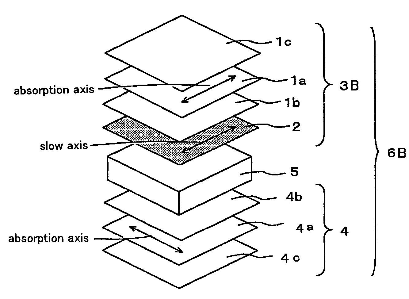
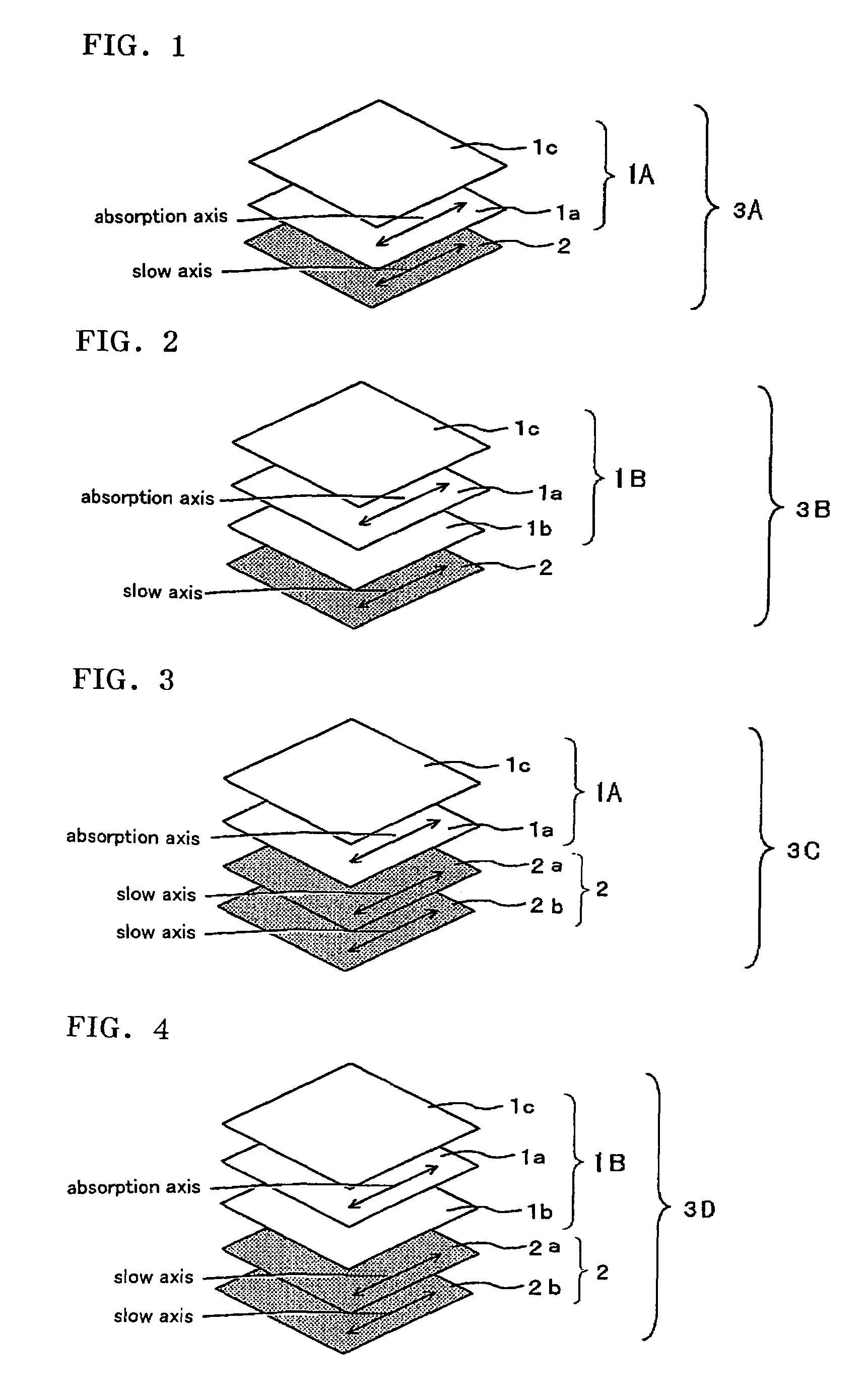
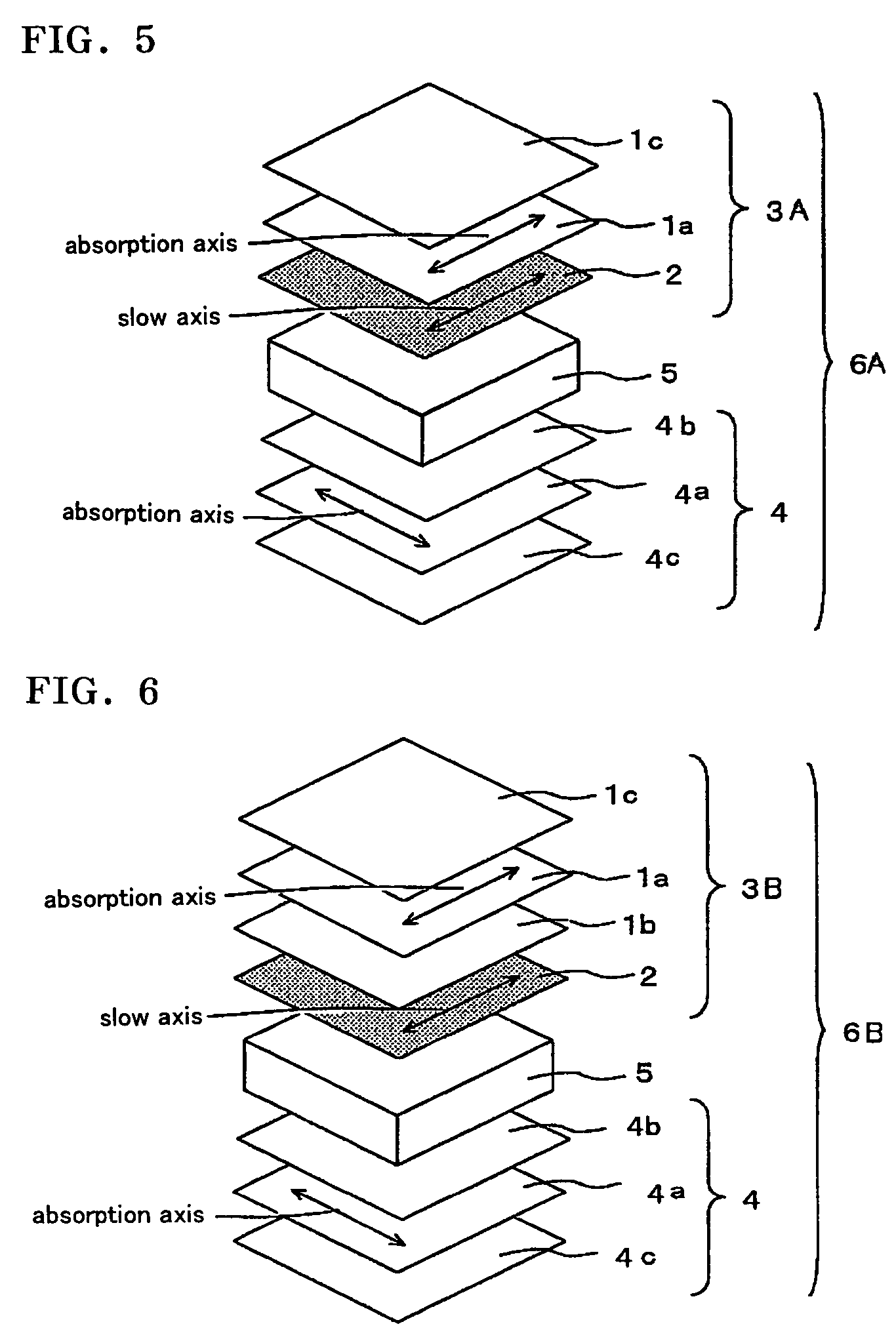
  • Retardation film, process for producing the same, optical film, image display, liquid crystal panel and liquid crystal display
  • Retardation film, process for producing the same, optical film, image display, liquid crystal panel and liquid crystal display
  • Retardation film, process for producing the same, optical film, image display, liquid crystal panel and liquid crystal display

Examples


example 1

[0246]A shrinkable film (E) was applied on both sides of a polymer film (trade name “ZEONOR ZF14-100” manufactured by Nippon Zeon Co., Ltd.) having thickness of 100 μm containing a resin in which a ring opening polymer obtained by polymerizing a norbornene-based monomer had been hydrogenated, via an acrylic resin-based pressure-sensitive adhesive layer (thickness 15 μm). Thereafter, a film was retained at the machine direction with a roll stretching machine, and the film was stretched at 1.38 times in an air circulating constant temperature oven at 146° C.±1° C. Properties of the resulting retardation film are as shown in Table 2. A glass transition temperature (Tg) of the polymer film containing a resin in which a ring opening polymer obtained by polymerizing a norbornene-based monomer had been hydrogenated was 136° C., a retardation value in film plane before stretching was 5.0 nm, and a retardation value in the thickness direction was 12.0 nm.

[0247]As the acrylic resin-based pres...

example 2

[0248]According to the same manner as that of Example 1 except that a stretching temperature was changed from 146° C. to 140° C., and a stretching ratio was changed from 1.38 times to 1.08 times, a retardation film was prepared. Properties of the resulting retardation film are shown in Table 2.

example 3

[0249]According to the same manner as that of Example 1 except that a stretching temperature was changed from 146° C. to 140° C., and a stretching ratio was changed from 1.38 times to 1.09 times, a retardation film was prepared. Properties of the resulting retardation film are shown in Table 2.


PUM

PropertyMeasurementUnit
polymerization pressureaaaaaaaaaa
glass transition temperatureaaaaaaaaaa

Abstract

A retardation film of the present invention comprises a stretched film of a polymer film containing a norbornene-based resin, wherein the stretched film satisfies the following equation (1) and the equation (2); 100 nm≦(nx−ny)·d≦350 nm . . . (1), 0.1≦(nx−nz) / (nx−ny)≦0.9 . . . (2), where the refractive indices in the slow axis direction, the fast axis direction and the thickness direction of the film are nx, ny and nz, respectively, d(nm) is thickness of the film, and the slow axis direction is a direction that the refractive index in film plane is maximum. The retardation film is hard to cause a shift or an unevenness of a retardation value due to a stress.

Description

BACKGROUND OF THE INVENTION[0001]1. Field of the Invention[0002]The present invention relates to a retardation film and a process for producing the same. The present invention also relates to an optical film as a combination of the retardation film and a polarizer or a polarizing plate. The retardation film and the optical film can be applied to an image display such as a liquid crystal display, an organic EL display, and PDP. In particular, the retardation film of the present invention is suitable for compensating for a viewing angle of a liquid crystal cell of TN mode, VA mode, IPS mode, FFS mode or OCB mode, and an optical film using the retardation film can be suitably applied to a liquid crystal panel, and a liquid crystal display.[0003]2. Description of the Related Art[0004]In a liquid crystal display, generally, a liquid crystal panel in which a polarizer is disposed on both sides of a liquid crystal cell is used. In addition, in the liquid crystal panel, in order to opticall...

Claims


Application Information

Patent Timeline
Patent Type & Authority Patents(United States)
IPC IPC(8): G02B6/00G02F1/1335
CPCG02B5/3083G02B27/286G02F1/133634B29C55/12G02F1/133528
Inventor KAWAHARA, SATORUHAYASHI, MASAKIYANO, SHUUJIYODA, KENJIKOBAYASHI, KENTAROU
Owner NITTO DENKO CORP
Learn More