
Bi-frequency symmetrical patch antenna

a patch antenna and bi-frequency technology, applied in the direction of separate antenna unit combinations, resonance antennas, radiating element structural forms, etc., can solve the problems of insufficient bandwidth and integration difficulties, and the bi-frequency antenna still has drawbacks, so as to enhance the directionality the bandwidth range of the bi-frequency antenna

Inactive Publication Date: 2007-05-08
SMARTANT TELECOMM
View PDF3 Cites 14 Cited by
  • Summary
  • Abstract
  • Description
  • Claims
  • Application Information

AI Technical Summary

Benefits of technology

[0005]In view of the aforesaid problems, the primary object of the present invention is to provide a bi-frequency symmetrical patch antenna that has bi-frequency symmetrical radiation units to radiate feed-in signals and increase the bandwidth range of a bi-frequency antenna. The bi-frequency symmetrical radiation units are arranged in an array fashion to enhance the directionality of the bi-frequency antenna.
[0012]By means of the bi-frequency symmetrical patch antenna of the invention, the bi-frequency symmetrical radiation unit can receive a feed-in signal to increase the bandwidth range of the bi-frequency antenna. The power distribution unit can evenly distribute the feed-in power, corresponding to the feed-in signal, to each bi-frequency symmetrical radiation unit. The bi-frequency symmetrical radiation unit may be arranged in an array fashion to enhance the directionality of the bi-frequency antenna.

Problems solved by technology

This causes inconvenience.
However, the present bi-frequency antenna still has drawbacks, such as an insufficient bandwidth and integration difficulties.

Method used


Image

  • Bi-frequency symmetrical patch antenna
  • Bi-frequency symmetrical patch antenna
  • Bi-frequency symmetrical patch antenna

Examples


first embodiment

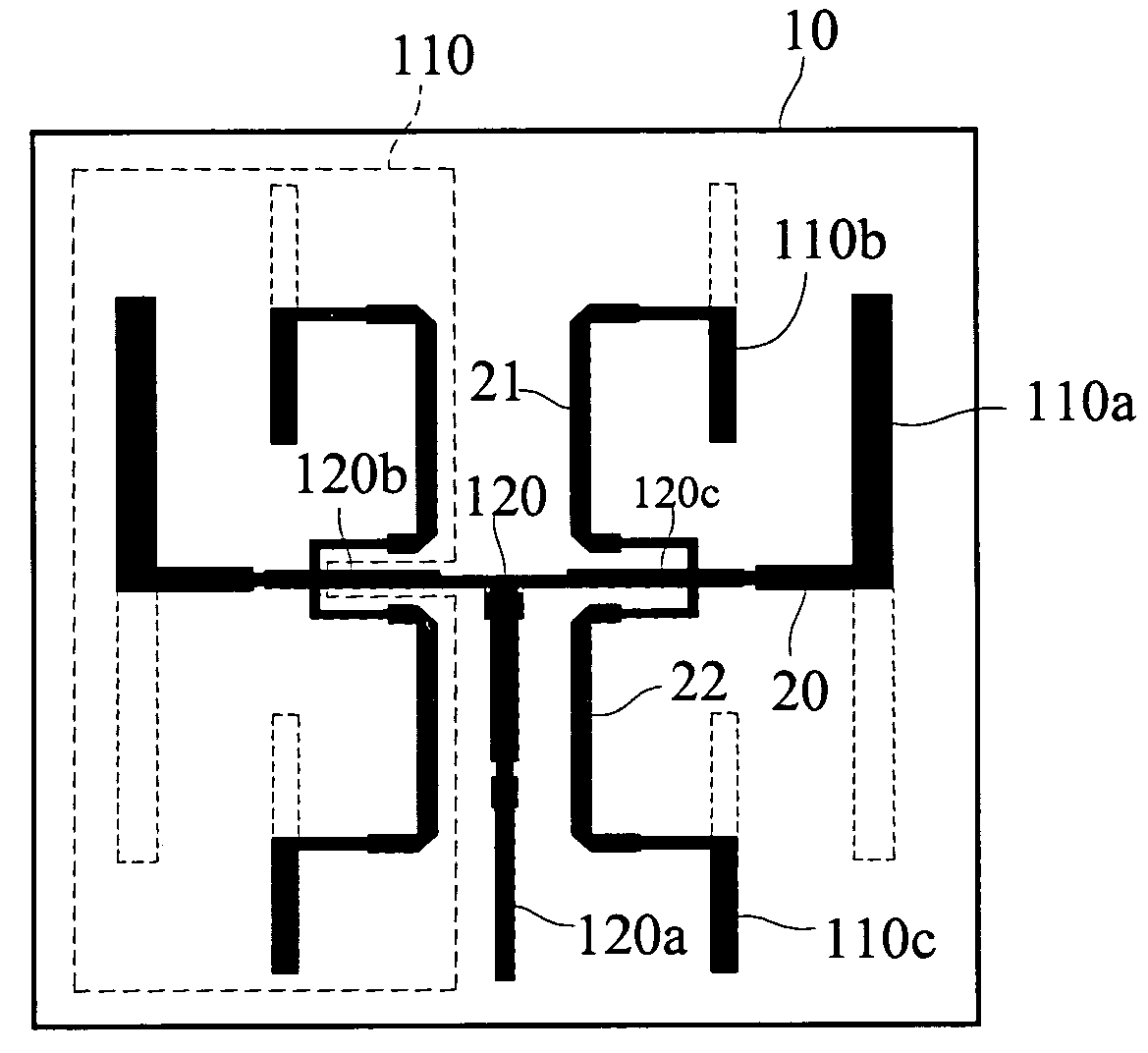
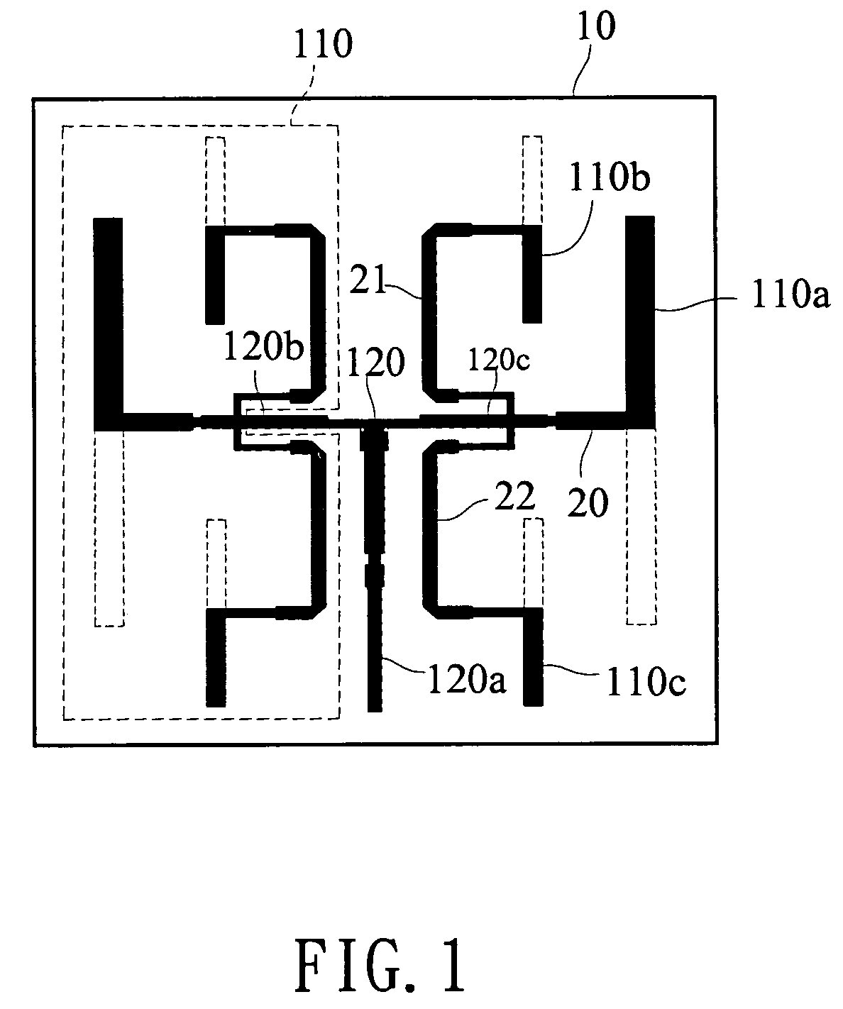
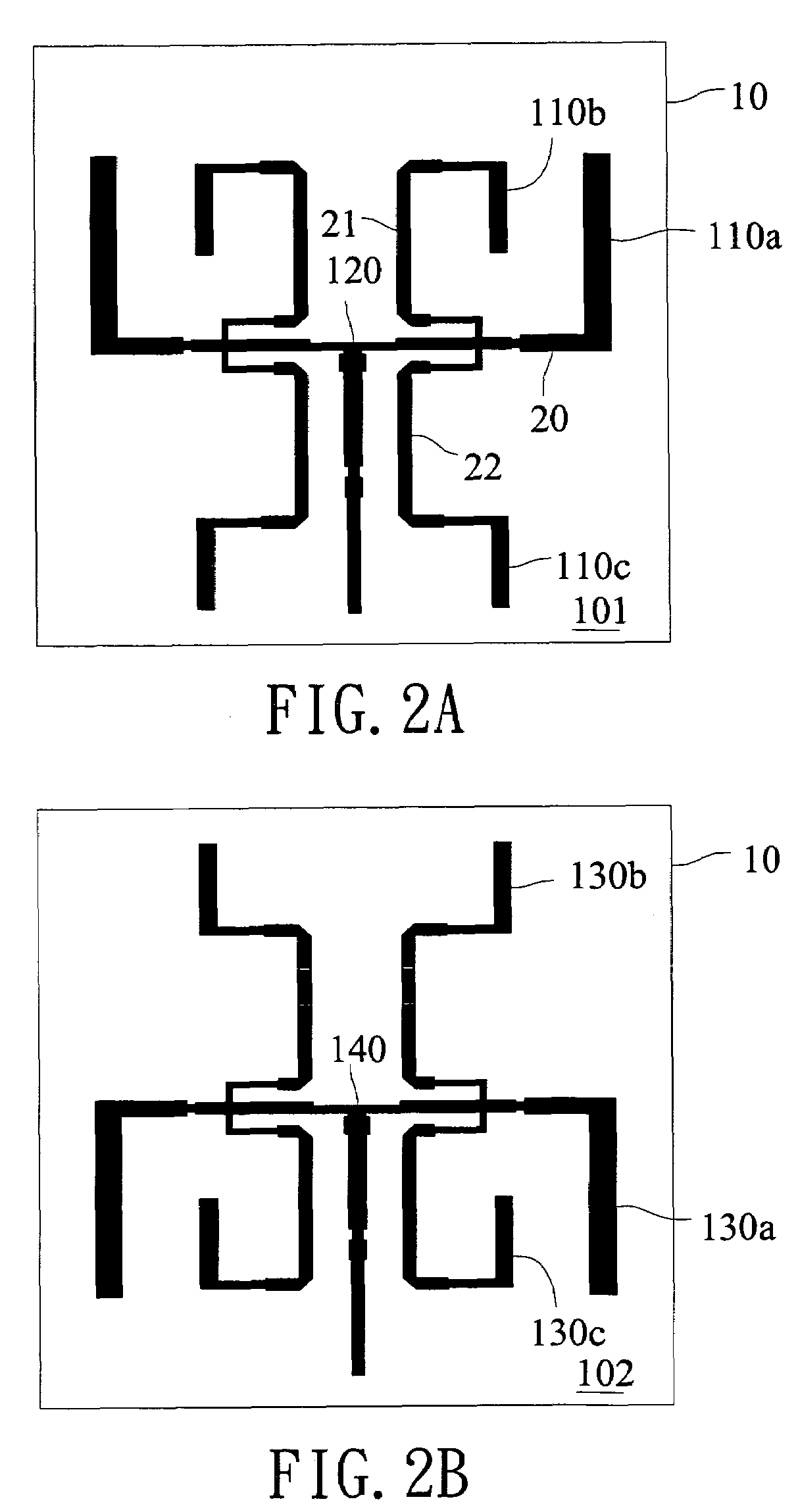
[0024]Refer to FIG. 2A for the front view of the first surface of the invention. The first surface 101 has a micro strip circuit pattern of the circuit layer. In the center of the antenna baseboard 10, there is a power distribution unit 120. A radio signal feeds in through a distal end 120a of the power distribution unit 120. There are bi-frequency symmetrical radiation units 110, connecting respectively to two side arms 120b and 120c, to form a completed antenna pattern. The power distribution unit 120 evenly distributes feed-in power corresponding to the feed-in signal to each of the bi-frequency symmetrical radiation units 110.

[0025]The bi-frequency symmetrical radiation units 110 have a first band radiation section 110a and second band radiation sections 110b and 110c. The first band (such as 2.4 GHz) radiation section 110a is located on one side of a distal end of a first micro strip 20 and vertically connected to one side of the distal end of the first micro strip wire 20.

[002...

second embodiment

[0031]Refer to FIG. 3 for a schematic view of the antenna baseboard of the invention. The bi-frequency symmetrical radiation units are arranged in an array fashion through the power distribution units and connected to one another. The schematic view includes a first bi-frequency symmetrical radiation unit 111, a second bi-frequency symmetrical radiation unit 112, a third bi-frequency symmetrical radiation unit 113, a fourth bi-frequency symmetrical radiation unit 114, a first power distribution unit 121, a second power distribution unit 122, a third power distribution unit 123, a fourth power distribution unit 124, a fifth power distribution unit 125, a sixth power distribution unit 126, and a seventh power distribution unit 127.

[0032]The first bi-frequency symmetrical radiation unit 111, second bi-frequency symmetrical radiation unit 112, third bi-frequency symmetrical radiation unit 113, and fourth bi-frequency symmetrical radiation unit 114 are formed in an antenna pattern same a...


PUM


Abstract

A bi-frequency symmetrical patch antenna includes two bi-frequency symmetrical radiation units, each having a first band radiation section and two second band radiation sections, to radiate a feed-in signal in a selected direction. Further, the antenna has a power distribution unit, to evenly distribute the feed-in power, corresponding to the feed-in signal, to each bi-frequency symmetrical radiation unit. The power distribution unit has two side arms connecting respectively to each bi-frequency symmetrical radiation unit to increase the bandwidth range of the bi-frequency antenna.

Description

FIELD OF THE INVENTION[0001]The present invention relates to a patch antenna and particularly to a bi-frequency symmetrical patch antenna.BACKGROUND OF THE INVENTION[0002]With continuous developments of wireless communication technology, nowadays users can transmit information through wireless communication systems without geometric restrictions. An antenna is one of the important elements in wireless communication. At present the antenna made from a printed circuit board is most popular. It is easier to fabricate and costs less.[0003]The commonly used wireless communication standards now are IEEE802.11 a and IEEE802.11b announced by the Electrical and Electronic Engineering Institute (IEEE). IEEE802.11a is for the band of 5 GHz. IEEE802.11b is for the band of 2.4 GHz. Design of the antenna baseboard has to comply with the corresponding bandwidth. If a wireless communication system has to be used in two different bands at the same time, matching antennas have to be provided. This ca...

Claims


Application Information

Patent Timeline
Patent Type & Authority Patents(United States)
IPC IPC(8): H01Q1/38
CPCH01Q9/285H01Q21/062H01Q5/48H01Q5/42H01Q21/30
Inventor SONG, JIA-JIUCHENG, WEI-TONG
Owner SMARTANT TELECOMM
Learn More