
Temperature-compensated fiber grating packaging arrangement

a technology of fiber grating and packaging arrangement, which is applied in the direction of optical waveguide light guide, optical light guide, instrument, etc., can solve the problems of temperature sensitivity of the grating device, the general size of the device is rather large, and the operation is often cumbersome, so as to reduce the strain along the fiber grating, the effect of compact and robust passive arrangement and stable operation

Inactive Publication Date: 2007-05-01
FURAKAWA ELECTRIC NORTH AMERICA INC
View PDF20 Cites 0 Cited by
  • Summary
  • Abstract
  • Description
  • Claims
  • Application Information

AI Technical Summary

Benefits of technology

[0011]It is an advantage of the present invention that the combination of a low CTE lever and high CTE expansion element results in a relatively compact and robust passive arrangement that remains stable in operation.
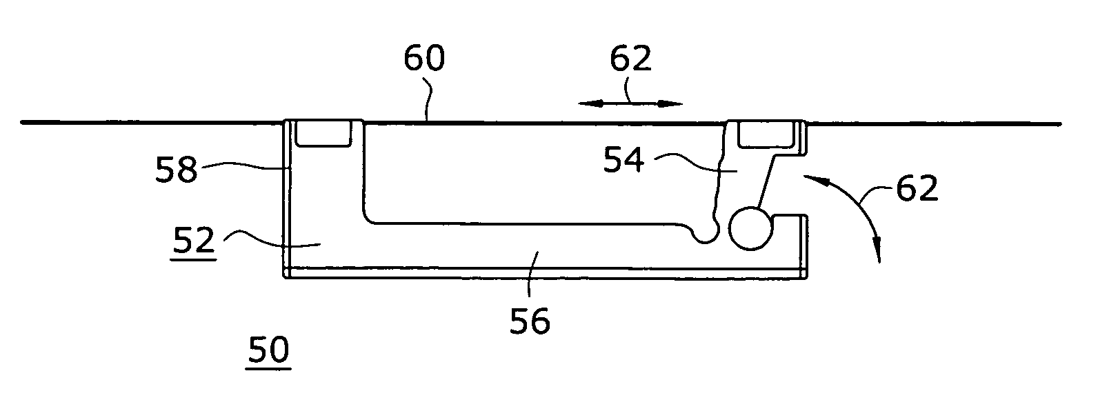
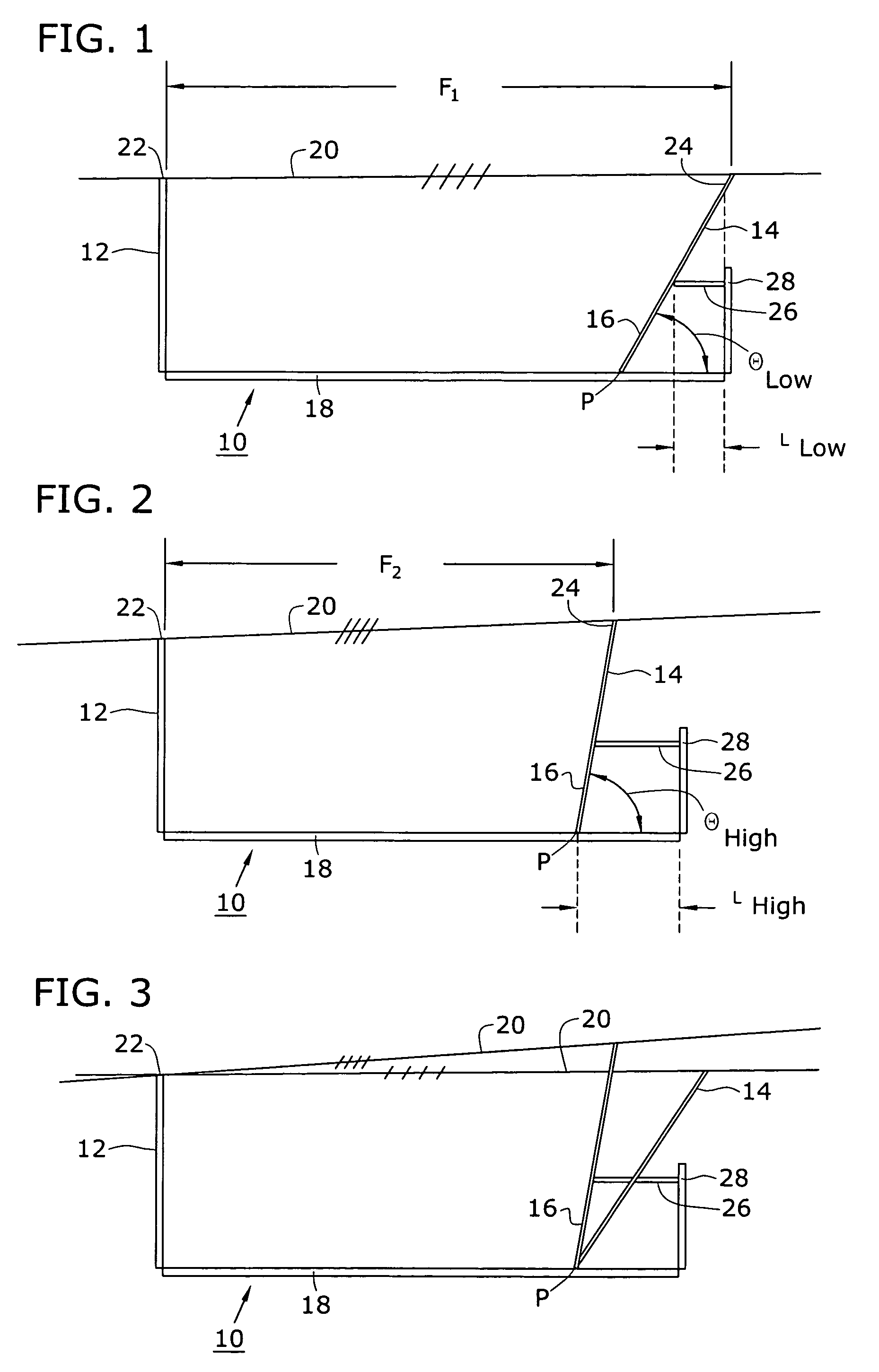
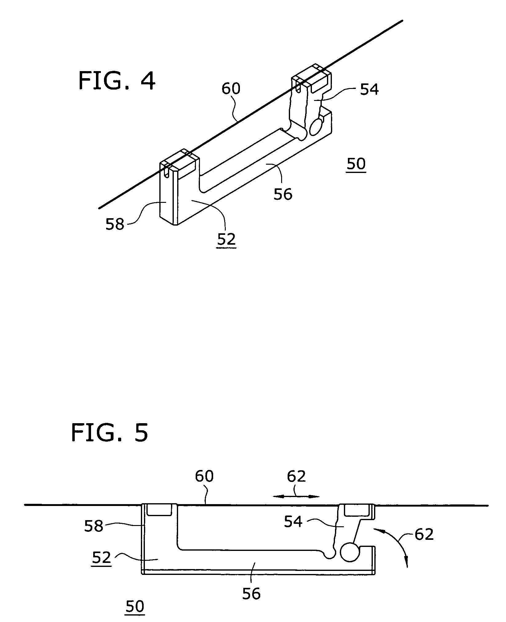
[0012]In one embodiment, the expansion element comprises an expansion arm disposed between a frame sidewall and the lever, such that the lever's angle with respect to the frame floor will increase as the temperature increases (thus reducing strain along the fiber grating and maintaining a constant wavelength). In an alternative embodiment, the high CTE element is embedded within the frame so as to be in physical contact with the lever and create the required angular movement to provide the desired temperature compensation.

Problems solved by technology

A common difficulty with all of these grating devices is temperature sensitivity.
While such a temperature-induced wavelength shift can be avoided by operating the grating device in a constant temperature environment, this approach requires the use of expensive and relatively bulky equipment to maintain the constant temperature.
While these and other devices have been useful in providing temperature compensation for fiber gratings, the devices are in general rather large in size and oftentimes cumbersome to operate.

Method used


Image

  • Temperature-compensated fiber grating packaging arrangement
  • Temperature-compensated fiber grating packaging arrangement
  • Temperature-compensated fiber grating packaging arrangement

Examples


Embodiment Construction

[0020]The passive temperature-compensated fiber grating device of the present invention is based on the principle that the fiber grating is sensitive to changes in both temperature T and strain ε, where an increase in temperature shifts the grating center wavelength to the longer side and a decrease in strain shifts the grating center wavelength to the shorter side. Thus, to maintain the desired center wavelength, any change in temperature can be compensated by a corresponding change in strain. In order to better understand the operation of the passive temperature compensated fiber grating of the present invention, it is useful to understand the underlying mathematical concepts associated with temperature and strain conditions. For a Bragg grating, the Bragg wavelength as a function of temperature (T) and strain (ε) can be represented as:

λ(T,ε)=2nΛ

where n is the reflection index and Λ is the grating period. Their partial differential results are:

[0021]∂λ∂T=2⁢n⁢∂Λ∂T+2⁢Λ⁢∂n∂T;∂λ∂ɛ=2⁢n...


PUM


Abstract

A passive temperature-compensated optical grating arrangement includes a housing of low CTE material, with the optical grating stretched across the housing between a first, fixed sidewall and a lever arm, the lever arm also being formed of a low CTE material. An expansion element of high CTE material is attached to the frame and disposed to contact the lever arm, resulting in rotating the lever arm as changes in temperature change the dimensions of the expansion element. By properly sizing the lever arm and the expansion element, changes in grating wavelength as a function of temperature can be compensated for by adjusting the strain applied to the grating as it is pulled or compressed as the lever arm is moved.

Description

TECHNICAL FIELD[0001]The present invention relates to a temperature-compensated fiber grating and, more particularly, to a fiber grating housed in a frame of low CTE material that includes a lever arm of low CTE material attached to the fiber grating. An expansion member of high CTE material, coupled to the lever arm, is to adjust the length of the grating so as to compensate for temperature-induced changes in the center wavelength of the grating.BACKGROUND OF THE INVENTION[0002]Optical gratings are important elements for selectively controlling specific wavelengths of light within optical systems. Such gratings include Bragg gratings, long period gratings and diffraction gratings and typically comprise a body of material and a plurality of substantially equally spaced optical grating elements, such as index perturbations, slits or grooves.[0003]A typical Bragg grating comprises a length of optical waveguide, such as an optic fiber, including a plurality of index perturbations subst...

Claims


Application Information

Patent Timeline
Patent Type & Authority Patents(United States)
IPC IPC(8): G02B6/00G02B6/34G02B6/02
CPCG02B6/0218
Inventor HUANG, HENRY
Owner FURAKAWA ELECTRIC NORTH AMERICA INC
Learn More