Data assurance method for optical storage media and optical storage device
- Summary
- Abstract
- Description
- Claims
- Application Information
AI Technical Summary
Benefits of technology
Problems solved by technology
Method used
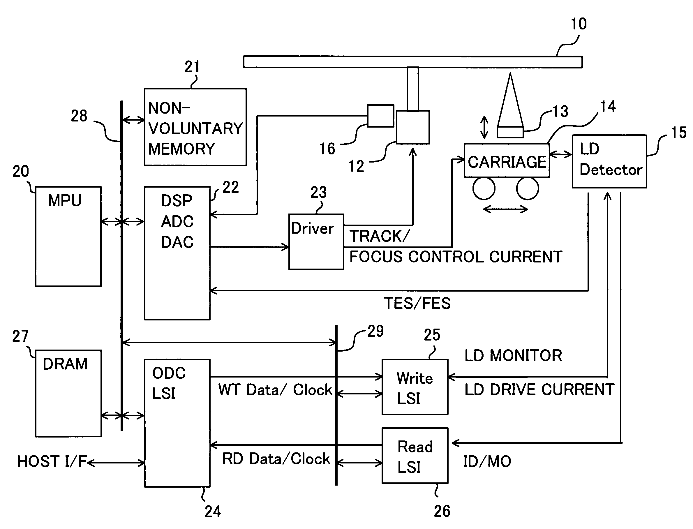
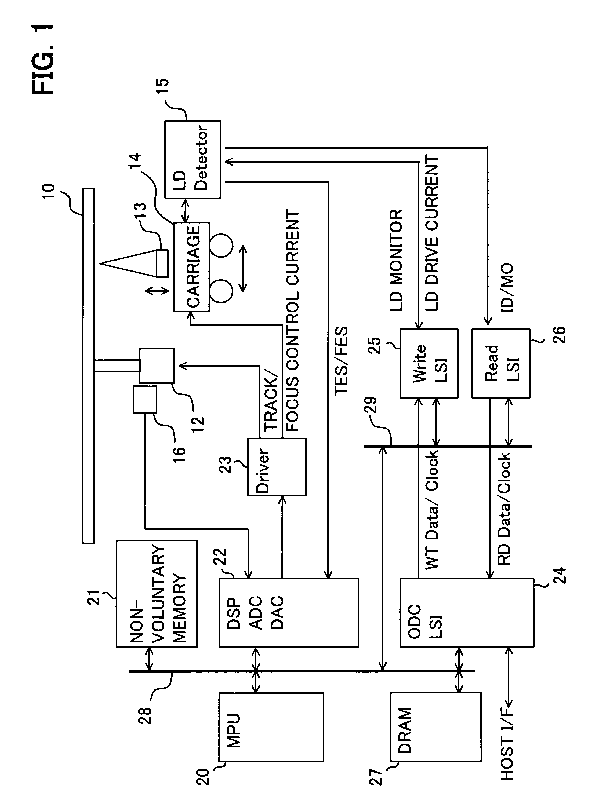
Image

Examples
first embodiment
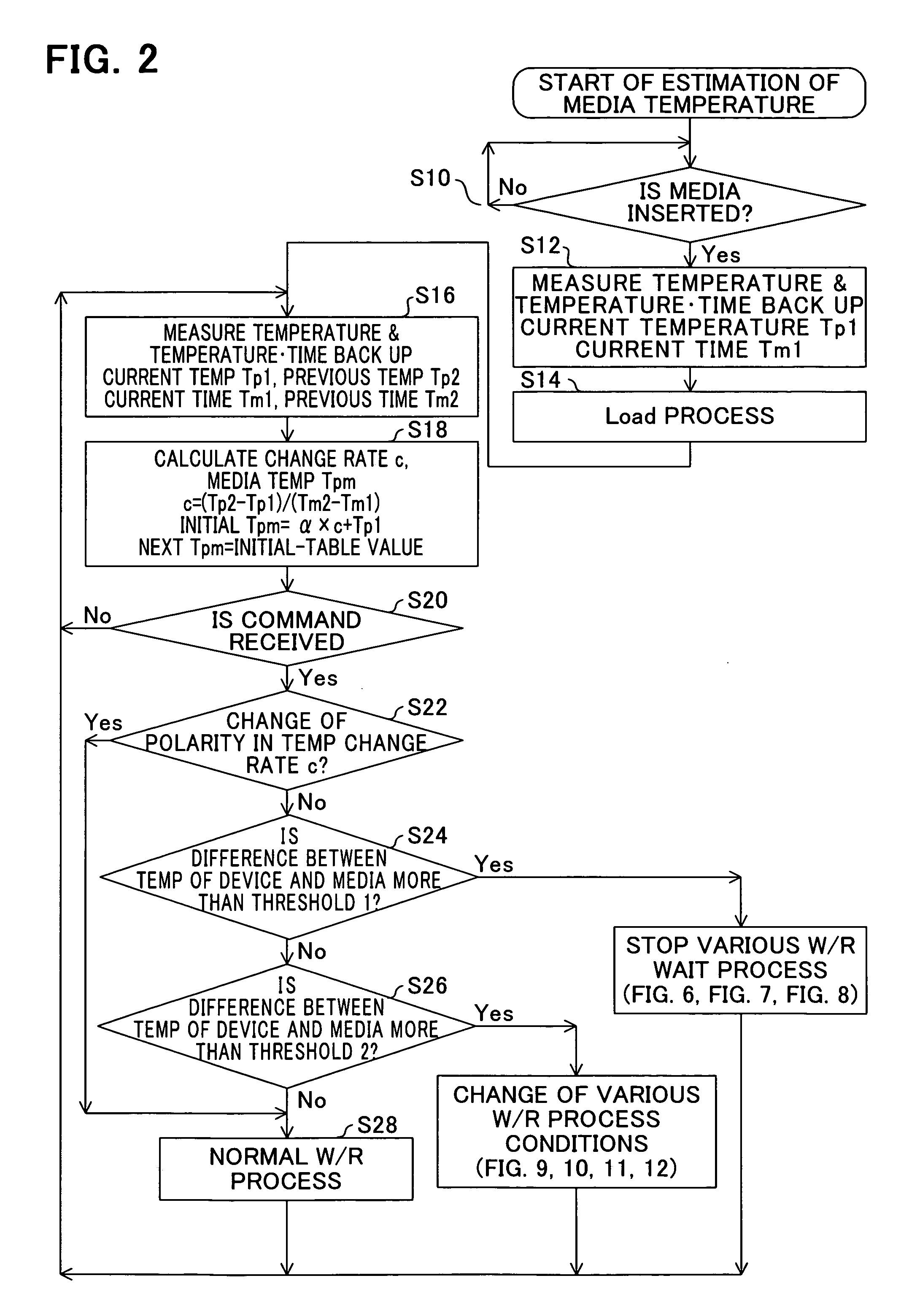
[0082]Next, the W / R halt / wait processing of FIG. 2 is explained. FIG. 6 shows the flow of processing of the W / R halt / wait processing of FIG. 2.
[0083](S30) Waiting continues for a predetermined length of time.
[0084](32) After waiting, W / R processing is performed under normal W / R conditions.
[0085]As shown in the above FIG. 3 and FIG. 4, when in this method a prescribed length of time (for example, 200 seconds) has elapsed from media insertion, the temperature difference between device and media has become small, and so by waiting the prescribed length of time, W / R processing is possible under normal conditions. In this case, it is preferable that this wait state be displayed by a device indicator and on the display of the higher-level device.
second embodiment
[0086]FIG. 7 shows the flow of processing in the W / R halt / wait processing of FIG. 2.
[0087](34) An error response is returned to the higher-level device, and processing ends.
[0088]In this method, when the temperature difference is such that W / R processing with assurance of data integrity cannot be performed immediately even when the W / R conditions (for example, the write power) are changed, an error is returned to the host to indicate this state.
third embodiment
[0089]FIG. 8 shows the flow of processing in the W / R halt / wait processing of FIG. 2.
[0090](S36) The media is ejected, halt processing ends, and processing returns to step S10 in FIG. 2.
[0091]In this method, when the temperature difference is such that W / R processing cannot be performed immediately with data integrity assured even when the W / R conditions (for example, the write power) changed, the media is ejected and processing is halted. In this case, the device responds to the host with a media ejection message.
[0092]These operations may be performed singly or in a plurality of combinations as necessary. For example, in the second embodiment, when prioritizing safety, it is to respond an error to the host immediately, to prevent data loss.
[0093]In the first embodiment, in order to prioritize safety, write / read execution is executed only after waiting for a stipulated length of time. It is expected that the temperature difference between media and device will become small during th...
PUM
 Abstract
Description
Claims
Application Information
 - R&D
- Intellectual Property
- Life Sciences
- Materials
- Tech Scout
- Unparalleled Data Quality
- Higher Quality Content
- 60% Fewer Hallucinations
Browse by: Latest US Patents, China's latest patents, Technical Efficacy Thesaurus, Application Domain, Technology Topic, Popular Technical Reports.
© 2025 PatSnap. All rights reserved.Legal|Privacy policy|Modern Slavery Act Transparency Statement|Sitemap|About US| Contact US: help@patsnap.com